Waxing device for fabric production

A cloth and material feeding technology, which is applied to the cleaning device for processing textile materials, the device for coating liquid on the surface, and the configuration of equipment for processing textile materials. Operation and other problems, to achieve the effect of increasing waxing effect, convenient fixing and disassembly, and increasing cleanliness

Inactive Publication Date: 2020-04-03
湖州甬邦纺织品织造有限公司
View PDF7 Cites 0 Cited by
  • Summary
  • Abstract
  • Description
  • Claims
  • Application Information

AI Technical Summary

Problems solved by technology

[0003] The existing waxing device for fabric production has certain disadvantages in use. First, after the device is waxed, excess wax may remain and adhere to the device's feeding and discharging workbench, which is inconvenient to clean and affects the next operation. , is not conducive to people's use. In addition, during the process of use, the rollers of the device and the inlet and outlet racks are prone to jamming, and the bearings are more likely to pinch hands. The safety needs to be improved. When using, the waxing barrel It is easy to get dirty and the strength is not high enough, which affects the operation of the cloth and brings certain adverse effects to people's use process. Therefore, we propose a waxing device for cloth production

Method used


Image

  • Waxing device for fabric production
  • Waxing device for fabric production
  • Waxing device for fabric production

Examples


Embodiment 1

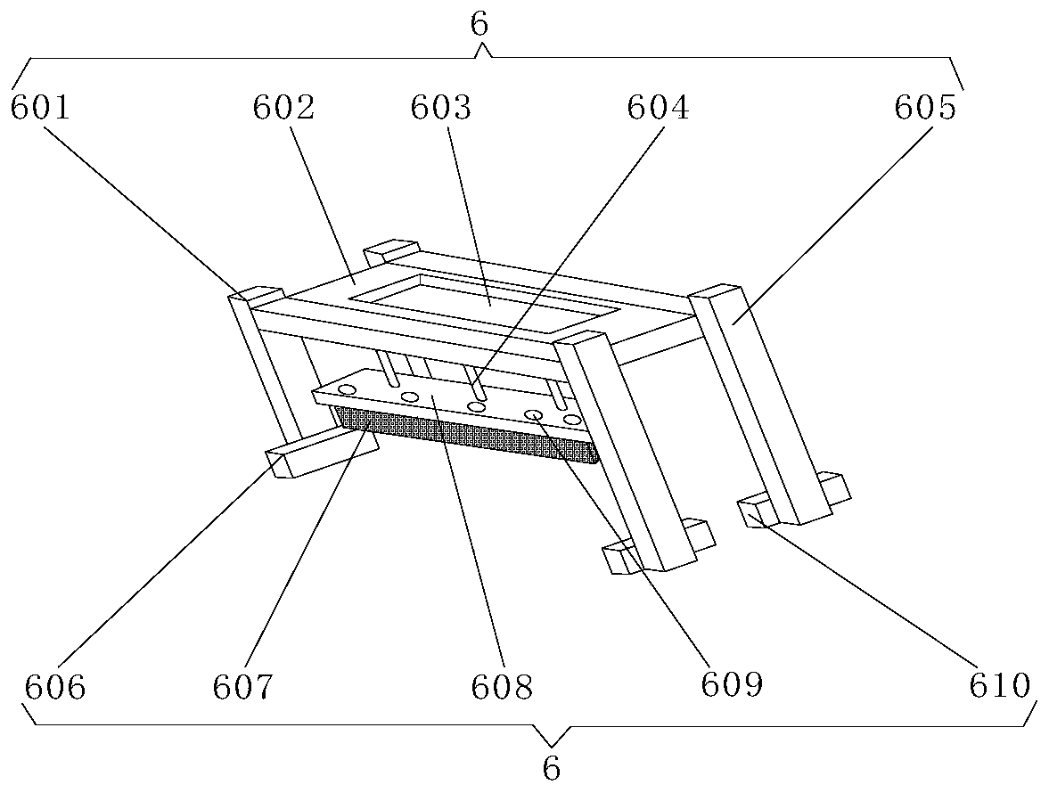
[0029] Embodiment one: if image 3 , 4As shown, the sliding type lifting cleaning rack mechanism 6 includes No. 1 support 601, support plate 602, placement groove 603, cylinder 604, No. 2 support 605, No. 1 slider 606, cleaning brush 607, cleaning plate 608, drip irrigation hole 609, No. 2 slider 610, support plate 602 is located inside the upper end of No. 1 bracket 601, No. 1 slider 606 is located inside the lower end of No. 1 bracket 601, placement slot 603 is located at the upper end of support plate 602, and No. 2 bracket 605 is located on support plate 602 On one side, the No. 2 slider 610 is located at the lower end side of the No. 2 support 605, the cylinder 604 is located at the lower end of the support plate 602, the cleaning plate 608 is located at the lower end of the cylinder 604, the drip irrigation hole 609 is located at the upper end of the cleaning plate 608, and the cleaning brush 607 Located at the lower end of the cleaning plate 608, a welding block is arr...

Embodiment 2

[0030] Embodiment two: if Figure 5 As shown, the detachable lubrication protection mechanism 8 includes a corner code 801, a shaft groove 802, a protective cover 803, a cover plate 804, a lubricating oil drip irrigation tank 805, and an observation window 806. The shaft groove 802 is located inside the protective cover 803, and the corner code 801 is located on one side of the protective cover 803, the lubricating oil drip irrigation tank 805 is located at the upper end of the protective cover 803, the cover plate 804 is located at the upper end of the lubricating oil drip irrigation tank 805, the observation window 806 is located at the front end of the protective cover 803, the corner code 801 and the protective cover 803 Screws are arranged between them, and one side of the corner code 801 is fixedly connected with one side of the protective cover 803 by screws, and a slot is provided between the protective cover 803 and the observation window 806, and the outer surface of ...

Embodiment 3

[0031] Embodiment three: as Figure 6 , 7 As shown, the self-cleaning discharge roller support mechanism 9 includes an anti-corrosion layer 901, a reinforcement layer 902, a rust removal layer 903, a secondary shaft 904, a self-cleaning layer 905, and a discharge roller 906. The secondary shaft 904 is located on the discharge roller 906 The self-cleaning layer 905 is located on the outer surface of the discharge roller 906, the anti-corrosion layer 901, the strengthening layer 902, and the rust removal layer 903 are all located inside the discharge roller 906, and the reinforcement layer 902 is located on the outer surface of the anti-corrosion layer 901 , the derusting layer 903 is located on the outer surface of the reinforcing layer 902, and a strong glue is arranged between the self-cleaning layer 905 and the discharge roller 906, and the outer surface of the discharge roller 906 passes through the superglue and the inner surface of the self-cleaning layer 905. The surfac...


PUM


Abstract

The invention discloses a waxing device for fabric production, and relates to the technical field of fabric production. The waxing device comprises a waxing device body; a waxing roller is arranged atthe inner side of the waxing device body; the upper end of the waxing roller is provided with a self-cleaning discharge roller bracket mechanism; a support is arranged at the front end of the waxingdevice body; and the upper end of the support is provided with a feeding support frame and a convenient disassembly and assembly type lubrication protection mechanism. According to the waxing device for the fabric production provided by the invention, a sliding type lifting cleaning rack mechanism, the convenient disassembly and assembly type lubrication protection mechanism and the self-cleaningdischarge roller bracket mechanism are arranged, the waxing device can be cleaned conveniently, wax materials on a discharge rack can be better removed, the cleanliness and aesthetics of the device are increased, the lubrication of the roller of the device is facilitated, the effect is excellent, a certain protective effect is achieved, the use function is increased, the better use of the discharge rack is facilitated, the service life is increased, the waxing device has a self-cleaning effect, the waxing effect is increased, and better use prospects are brought.

Description

technical field [0001] The invention relates to the technical field of cloth production, in particular to a waxing device for cloth production. Background technique [0002] The waxing device for fabric production is a supporting device for waxing the fabric during the fabric production operation. During the fabric production, the surface of the fabric needs to be treated to make the surface of the fabric smoother and more beautiful. Sometimes it is necessary to use a waxing device to wax the surface of the cloth, increase the use effect of the cloth, and facilitate the better use of the cloth. With the continuous development of science and technology, people are more concerned about the manufacturing process of the waxing device for cloth production. The requirements are also getting higher and higher. [0003] The existing waxing device for fabric production has certain disadvantages in use. First, after the device is waxed, excess wax may remain and adhere to the device'...

Claims


Application Information

Patent Timeline
Patent Type & Authority Applications(China)
IPC IPC(8): D06B1/14D06B23/30D06B23/04D06B23/20B05C5/02
CPCB05C5/0208D06B1/14D06B23/04D06B23/20D06B23/30
Inventor 杨海峰
Owner 湖州甬邦纺织品织造有限公司
Why Eureka
Try Eureka