Steel plate composite beam bridge support-free cast-in-place concrete device and construction method

A composite beam, no bracket technology, used in bridges, bridge parts, bridge materials, etc., can solve the problems of restricting the application of steel plate composite beams, insufficient bracket safety, reducing construction progress, etc., to prevent crack propagation problems, consistent thickness, The effect of speeding up the construction progress

Pending Publication Date: 2020-04-03
CHANGAN UNIV
View PDF0 Cites 4 Cited by
  • Summary
  • Abstract
  • Description
  • Claims
  • Application Information

AI Technical Summary

Problems solved by technology

This method needs to set up supports before construction, which will have a great impact on the traffic under the bridge. At the same time, making the supports on site will consume manpower and material resources, reducing the construction progress, and because the produced supports are temporary structures, there is a certain degree of Material waste and safety hazards
In addition, as the height

Method used


Image

  • Steel plate composite beam bridge support-free cast-in-place concrete device and construction method
  • Steel plate composite beam bridge support-free cast-in-place concrete device and construction method
  • Steel plate composite beam bridge support-free cast-in-place concrete device and construction method

Examples


Embodiment Construction

[0033] The present invention will be further described in detail below in conjunction with specific embodiments, which are explanations of the present invention rather than limitations.

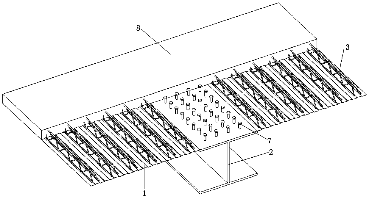
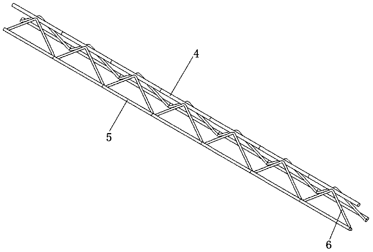
[0034] like figure 1 As shown, the cast-in-place concrete device for a steel plate composite girder bridge without support includes: a profiled steel plate 1, a steel girder 2, a steel skeleton 3 and a shear key 7.

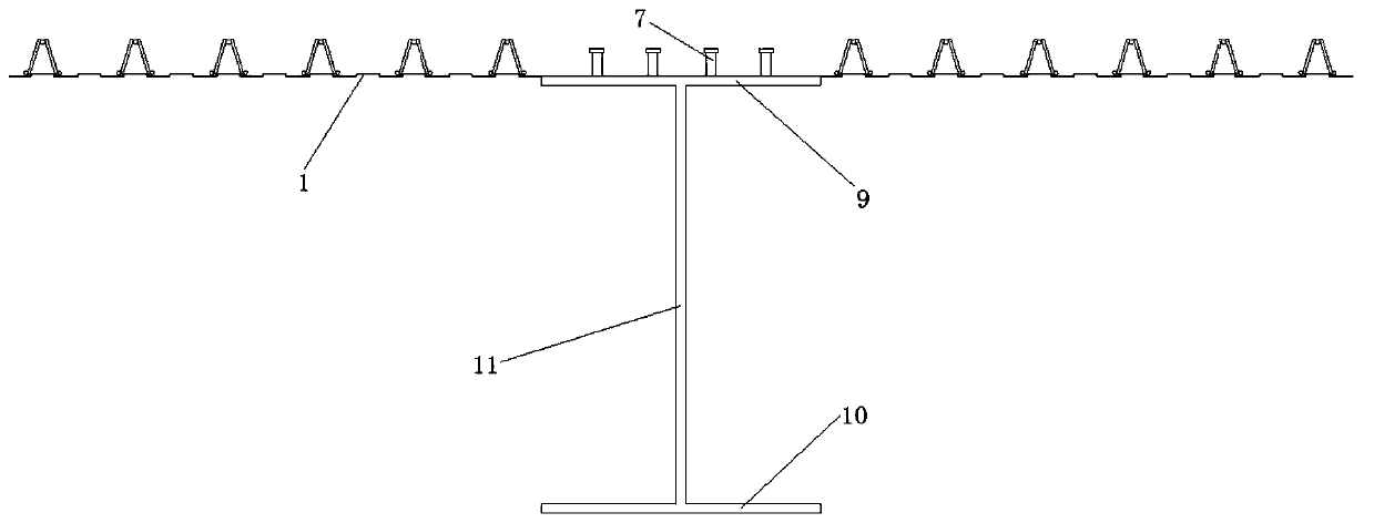
[0035] like figure 1 and figure 2 As shown, the cross-sectional shape of the steel beam 2 is I-shaped, including an upper flange 9, a lower flange 10, and a web 11 connecting the upper flange 9 and the lower flange 10. The top of the upper flange 9 of the steel beam 2 is provided with Shear key 7. The lower end of the shear key 7 is welded on the upper flange 9 of the steel girder 2, which is convenient for construction and ensures that the bridge deck 8 and the steel girder 2 are tightly connected.

[0036] In a specific embodiment, the thickness of the upper flange 9, the ...


PUM


Abstract

The invention discloses a steel plate composite beam bridge support-free cast-in-place concrete device and a construction method. The steel plate composite beam bridge support-free cast-in-place concrete device comprises profiled steel sheets, steel beams, steel reinforcement frameworks and shear connectors. The shear connectors are arranged on the upper flanges of the steel beams, the two sides of the upper flanges of the steel beams are each connected with a profiled steel sheet, and a plurality of steel bar frameworks are arranged on each profiled steel sheet. When the device is used for cast-in-place construction of the concrete bridge deck slab, a bracket is not required to be erected; the bearing capacity of the bridge deck slab is improved by the upper steel reinforcement frameworks; the profiled steel sheets at the bottom are used as a formwork, the bottom concrete is prevented from being subjected to slurry leakage, pitted surfaces, falling and other diseases, threats to pedestrians or vehicles passing under the bridge are avoided, meanwhile, the economical efficiency is good, construction is convenient and fast, the construction efficiency is remarkably improved, the construction cost is saved, and civilized construction and safe construction are convenient to achieve.

Description

technical field [0001] The invention relates to the field of steel plate composite girder bridges, in particular to a cast-in-place concrete device and construction method for steel plate composite girder bridges without supports. Background technique [0002] Most of the bridge deck constructions of existing steel plate composite girder bridges adopt supporting plates or templates to finalize the shape at the bottom of the bridge deck, and then pour reinforced concrete. This method needs to set up supports before construction, which will have a great impact on the traffic under the bridge. At the same time, making the supports on site will consume manpower and material resources, reducing the construction progress, and because the produced supports are temporary structures, there is a certain degree of Material waste and safety hazard. In addition, as the height of the bridge deck increases, the safety of the support is insufficient, and the economy becomes poor; when the ...

Claims


Application Information

Patent Timeline
IPC IPC(8): E01D21/00E01D19/12E01D101/26E01D101/30
CPCE01D19/125E01D21/00E01D2101/26E01D2101/30
Inventor 程高苏巨峰陈浩高双印程张刘纯
Owner CHANGAN UNIV
Why Eureka
Try Eureka