Electro-hydraulic brake-by-wire device with redundancy function and control method

An electro-hydraulic wire and functional technology, applied in the field of electro-hydraulic wire-controlled brake devices, can solve the problems of vehicle brake precision control, brake fluid pressure fluctuations, increase the length of brake pipelines, etc., to improve brake response Effects of speed and control accuracy, solving braking hysteresis, and shortening response time

Active Publication Date: 2020-04-10
SHANDONG JIAOTONG UNIV
View PDF7 Cites 1 Cited by
  • Summary
  • Abstract
  • Description
  • Claims
  • Application Information

AI Technical Summary

Problems solved by technology

[0005] Although the existing electronic hydraulic brake system (EHB) uses an electronic brake pedal, its brake pressure is provided by a plunger pump driven by a motor, and a high-pressure accumulator is used to store pressure, and the backup brake system More isolation solenoid valves are used in the system, so that the whole system has more parts and higher cost
In addition, in the existing braking system, the master cylinder and the pressure regulating unit are not integrated, the degree of modularization is not high, the length of the brake pipeline is increased, and the brake pressure response is slow
Since the brake pipeline will undergo elastic deformation under the action of high-pressure brake fluid, the pressure of the brake fluid in the brake pipeline will fluctuate, which will greatly affect the precise control of vehicle braking.

Method used


Image

  • Electro-hydraulic brake-by-wire device with redundancy function and control method
  • Electro-hydraulic brake-by-wire device with redundancy function and control method
  • Electro-hydraulic brake-by-wire device with redundancy function and control method

Examples


Embodiment Construction

[0043] In order to clearly illustrate the technical features of the solution, the solution will be described below through a specific implementation mode and in conjunction with the accompanying drawings.

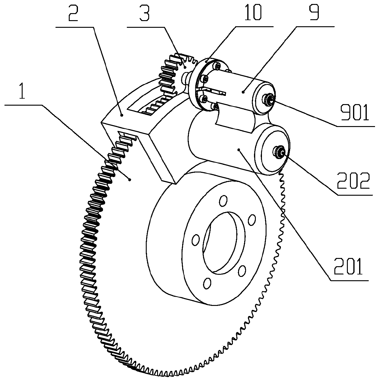
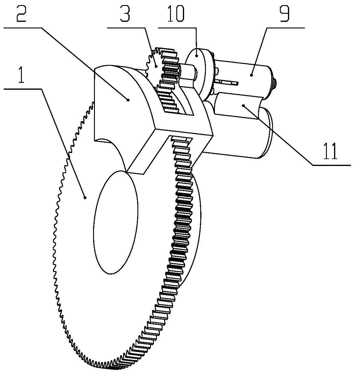
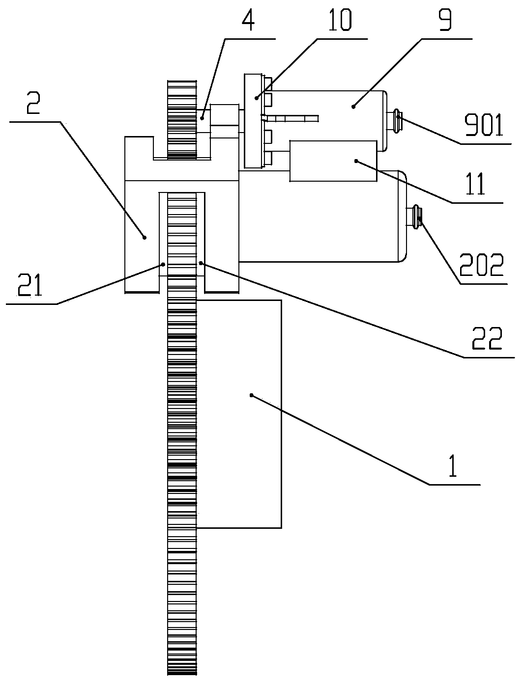
[0044] An electro-hydraulic brake-by-wire device with redundant functions such as figure 1 , figure 2 , image 3 with Figure 4 As shown, it includes brake disc 1, caliper 2, power take-off gear 3, gear shaft 4, lead screw 5, return spring 6, piston nut 7, sealing ring 8, high-pressure oil cylinder housing 9, electromagnetic clutch 10, and fixing seat 11. Hydraulic control unit 12, split fluid storage tank 13, accumulator 14, fluid storage tank 15, angle sensor 16, brake pedal 17, brake push rod assembly 18, brake master cylinder 19, controller 20, The left friction plate 21 and the right friction plate 22; the end cap on the brake disc 1 is fixedly installed on the wheel by bolts; the described caliper 2 is fixedly installed on the vehicle body, and the left friction p...


PUM


Abstract

The invention relates to an electro-hydraulic brake-by-wire device with a redundancy function and a control method. The device comprises a brake disc, calipers, a power take-off gear, a gear shaft, alead screw, a return spring, a piston nut, a sealing ring, a high-pressure oil cylinder shell, an electromagnetic clutch, a fixed seat, a hydraulic control unit, a split liquid storage tank, an energyaccumulator, a liquid storage tank, an angle sensor, a brake pedal, a brake push rod assembly, a brake master cylinder, a controller, a left friction plate and a right friction plate. Vehicle kineticenergy can be fully utilized as a power source, a driving motor is omitted, and the cost is effectively reduced. A gear power take-off mechanism is adopted to drive a high-pressure oil cylinder to generate high-pressure brake oil, and whether the high-pressure oil cylinder works or not is controlled through the electromagnetic clutch. The high-pressure oil cylinder is integrated on the brake oilcylinder, so that a brake pipeline is effectively shortened, brake pressure fluctuation caused by elastic deformation of the brake pipeline is reduced, and the brake response speed and the control precision are improved. The device has the advantages of high integration level, high response speed and low cost.

Description

technical field [0001] The invention relates to the field of automobile brakes, in particular to an electro-hydraulic wire-controlled brake device with redundant functions. Background technique [0002] Brake-by-wire technology is a new type of braking technology that has emerged in recent years. It does not rely on mechanical or hydraulic connections between the brake and the brake pedal. It uses wires to replace part or all of the brake pipelines, and controls the electronic control through the controller. The components are used to control the braking force and realize the stable and reliable braking control of the car. At present, the brake-by-wire system mainly includes two types: electro-hydraulic brake system (EHB) and electro-mechanical brake system (EMB). The brake-by-wire system is conducive to the optimization of the braking performance of the whole vehicle, and can be easily integrated with other electronic control systems such as ABS, ASR, ESP, etc., so it has ...

Claims


Application Information

Patent Timeline
Patent Type & Authority Applications(China)
IPC IPC(8): B60T13/14
CPCB60T13/145
Inventor 张竹林许本博蒋德飞戴汝泉菅秀文
Owner SHANDONG JIAOTONG UNIV
Why Eureka
Try Eureka