Gas injection oil production process in double-layer oil pipe

A double-layer tubing and process technology, which is applied in the fields of fluid production, earth-moving drilling, wellbore/well components, etc., can solve the problems of frequent string tripping and casing corrosion, and achieve the effect of saving operating costs and reducing leak detection.

Inactive Publication Date: 2020-04-10
库尔勒中油能源技术服务有限公司
View PDF6 Cites 2 Cited by
  • Summary
  • Abstract
  • Description
  • Claims
  • Application Information

AI Technical Summary

Problems solved by technology

[0008] The object of the present invention is to provide a gas injection and oil recovery process in double-layer tubing to solve the serious corrosion of the outer wall and casing of the tubing when nitrogen or na

Method used


Image

  • Gas injection oil production process in double-layer oil pipe
  • Gas injection oil production process in double-layer oil pipe

Examples


Embodiment

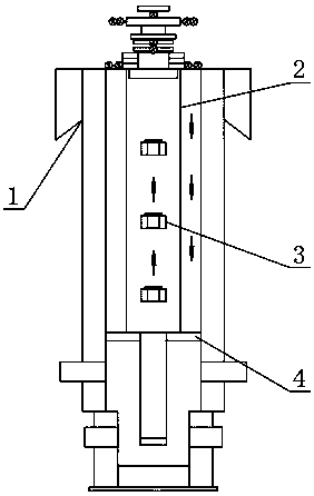
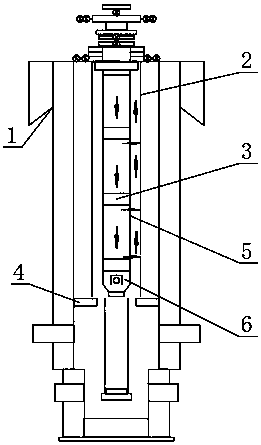
[0031] see figure 2 , the present invention provides a technical solution: a gas injection and oil recovery process in a double-layer oil pipe, the gas lift process is as follows:

[0032] Step 1: Lower the small oil pipe 5 into the main oil pipe 2, and install the gas lift valve 3 on the small oil pipe 5;

[0033] Step 2: Inject nitrogen or natural gas into the small oil pipe 5;

[0034] Step 3: The oil is discharged from the annular space of the small oil pipe 5 and the main oil pipe 2, and the gas lift production is carried out.

[0035] In this embodiment, preferably, the small oil pipe 5 is also provided with a POP check valve 6, and the POP check valve 6 and the small oil pipe 5 are connected by screwing, which helps to realize the POP check valve 6 and the small oil pipe 5. The installation and disassembly of the POP check valve 6 is set to avoid oil backflow.

[0036] In this embodiment, preferably, a packer 4 for sealing off the annular space is also included.

...


PUM


Abstract

The invention discloses a gas injection oil production process in a double-layer oil pipe. The gas lift process comprises the following steps that a small oil pipe is put into a main oil pipe, and a gas lift valve is arranged on the small oil pipe; nitrogen or natural gas is injected into the small oil pipe; and oil is discharged from the annular spaces of the small oil pipe and the main oil pipe,and gas lift production is carried out. The process has the beneficial effects that when a conventional gas lift pipe column is injected with nitrogen or natural gas, the outer wall of an oil pipe and a casing pipe are seriously corroded, the casing pipe can be well protected from being corroded, and oxygen-containing gas does not directly contact the casing pipe; a gas exchange lifting pipe column or a gas injection pipe column of an original well production pipe column is avoided, the well repairing period is reduced, the yield is improved, and the operation cost is saved; and later leakagefinding, leakage blocking and channeling plugging workover are reduced, and operation cost is saved.

Description

technical field [0001] The invention belongs to the technical field of gas lift production, and in particular relates to a gas injection and oil production process in a double-layer oil pipe. Background technique [0002] In the production process of many self-spraying oil and gas wells in the oilfield, due to the accumulation of liquid in the wellbore or the production string of the formation water, the self-spraying cannot be performed. way of production. [0003] Gas lift oil recovery: relying on the high-pressure gas injected from the surface into the well to mix with the fluid produced from the oil layer in the wellbore, the expansion of the gas is used to reduce the density of the mixed liquid in the wellbore, and the crude oil flowing into the well is lifted to the surface. [0004] Run the small tubing + in-pipe concentric gas lift valve into the existing production tubing string to implement secondary completion, inject nitrogen or natural gas into the small tubing...

Claims


Application Information

Patent Timeline
IPC IPC(8): E21B43/12E21B43/16
CPCE21B43/122E21B43/123E21B43/168
Inventor 蔡伟李军李跃进
Owner 库尔勒中油能源技术服务有限公司
Why Eureka
Try Eureka