
Strong coupling frequency selective surface structure insensitive to all angles of incident electromagnetic waves

A frequency selective surface and electromagnetic wave technology, applied in the field of metasurfaces, can solve the problems of FSS operating frequency deviation, system performance degradation, unfavorable engineering realization, etc., and achieve the effect of transmission zero point stability, overall weight reduction, and good angular stability

Pending Publication Date: 2020-04-10
海宁利伊电子科技有限公司
View PDF0 Cites 5 Cited by
  • Summary
  • Abstract
  • Description
  • Claims
  • Application Information

AI Technical Summary

Problems solved by technology

However, the FSS structure is often very sensitive to the incident angle. As the incident angle changes, the operating frequency of the FSS will shift, resulting in a decrease in system performance. How to improve the angular performance of the frequency selective surface becomes a major challenge.
In addition, with the development of high-frequency and high-speed communication and high-integration functional devices such as chip packaging, the size of the traditional frequency-selective surface structure based on wave physical resonance needs to be compared with the operating frequency wavelength, resulting in a large structure that is not conducive to engineering implementation and The demand for system miniaturization makes the ultra-miniature and ultra-thin FSS structure that can be applied in a small space such as chip packaging another big challenge

Method used


Image

  • Strong coupling frequency selective surface structure insensitive to all angles of incident electromagnetic waves
  • Strong coupling frequency selective surface structure insensitive to all angles of incident electromagnetic waves
  • Strong coupling frequency selective surface structure insensitive to all angles of incident electromagnetic waves

Examples


Embodiment Construction

[0045] The present invention will be further described below in conjunction with the accompanying drawings.

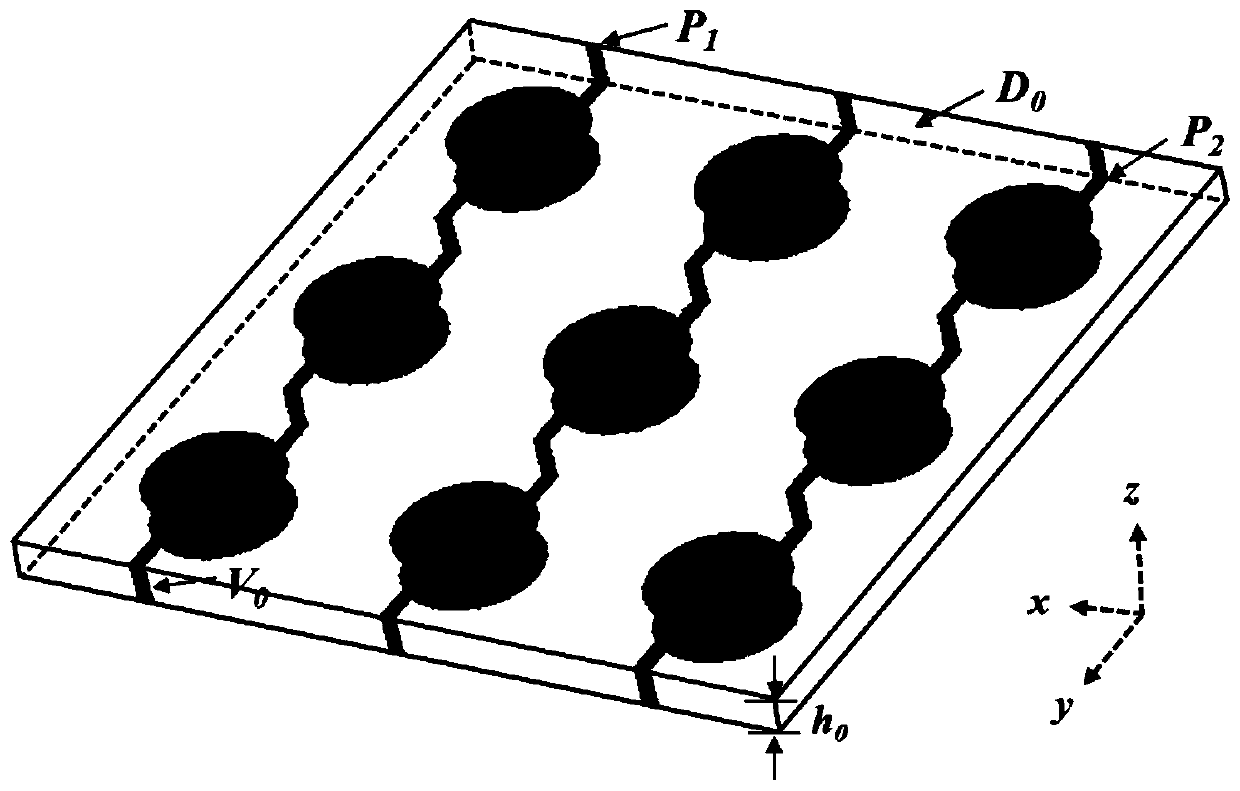
[0046] Such as figure 1 As shown, the implemented frequency selective surface structure includes a plurality of closely arranged periodic unit structures, and each periodic unit structure is mainly composed of a dielectric layer, two metal layers and metal vias connecting the two metal layers, wherein the two The first metal layer is attached to the two surfaces of the dielectric layer respectively.

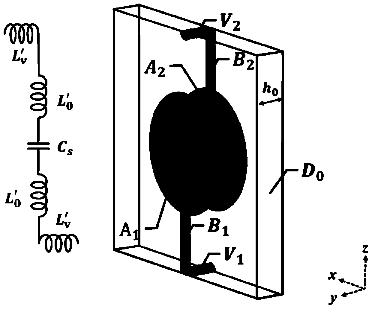
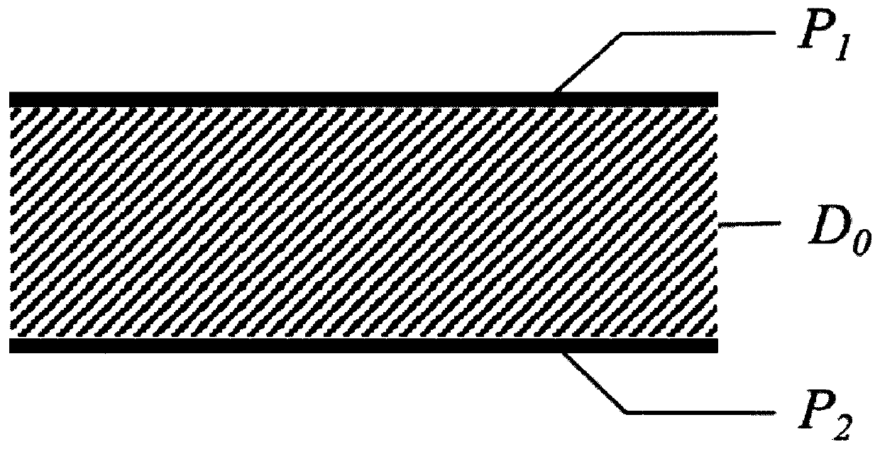
[0047] Such as figure 2 and image 3 As shown, the periodic unit structure includes the top metal patch P 1 , Dielectric board D 0 and the underlying metal patch P 2 , and connect the top metal patch P 1 and the underlying metal patch P 2 Metal vias between the upper and lower halves V 1 and V 2 Composition; top metal patch P 1 Attached to the medium plate D 0 Upper surface, bottom metal patch P 2 Attached to the medium board D 0 Bottom surface, underlying ...


PUM


Abstract

The invention discloses a strong coupling frequency selective surface structure insensitive to all angles of incident electromagnetic waves. The strong coupling frequency selective surface structure comprises a plurality of tightly-arranged periodic unit structures, and each periodic unit structure comprises top and bottom layer metal patches, a dielectric plate, an upper half metal via hole and alower half metal via hole; the top and bottom metal patches are respectively attached to the upper and lower surfaces of the dielectric plate and are stereosymmetrically arranged around the center ofthe dielectric plate; each of the top and bottom layer metal patches is formed by connecting a circular patch and a rectangular patch; the circular patches are arranged in the center of the surface of the dielectric plate, the half metal via holes are located in the middle of the upper / lower edge of the surface of the dielectric plate, and the circular patches and the half metal via holes are connected through the rectangular patches. The strong coupling frequency selective surface structure is suitable for frequency selective surface design with ultra-small and ultra-thin structures and wideincident angle stability, the unit size and thickness are extremely small, and the resonant frequency is stable and unchanged within the incident angle range of 0-88 degrees.

Description

technical field [0001] The invention relates to the technical field of metasurfaces, in particular to a strong-coupling frequency-selective surface structure insensitive to the full angle of incident electromagnetic waves, which can be applied to the design of ultra-miniature, ultra-thin structures and stable frequency-selective surfaces with wide incident angles. Background technique [0002] Frequency selective surfaces FSS (Frequency selective surfaces), also known as spatial filters, usually consist of two-dimensional periodic structures. It has the function of transmitting, reflecting or absorbing the incident electromagnetic wave at a specific frequency, so it is widely used in the design of high-performance radome radome, antenna reflector, space electromagnetic interference shielding and absorber, and electromagnetic stealth. [0003] In the past two decades, a large number of experts and scholars have conducted in-depth research on frequency selective surfaces, from...

Claims


Application Information

Patent Timeline
Patent Type & Authority Applications(China)
IPC IPC(8): H01Q15/00H01Q1/42H01Q17/00G01S7/02
CPCG01S7/02G01S7/027H01Q1/42H01Q15/0026H01Q17/008
Inventor 李尔平李天武秦鹏飞樊宇迪
Owner 海宁利伊电子科技有限公司
Learn More