Distributed harbor bank charging device

A charging device, port technology, applied in the direction of circuit devices, battery circuit devices, charging stations, etc., can solve the problems of charging device corrosion, moisture content, air humidity, water ingress, etc., and achieve the effect of easy protection

Pending Publication Date: 2020-04-10
国网山东省电力公司烟台市长岛供电公司
View PDF6 Cites 2 Cited by
  • Summary
  • Abstract
  • Description
  • Claims
  • Application Information

AI Technical Summary

Problems solved by technology

[0004] The purpose of the present invention is to provide a distributed port charging device in order to solve the above problems, which solves the problem that the existing charging devices are all installed at the port, so the moisture content in the air is relatively

Method used


Image

  • Distributed harbor bank charging device
  • Distributed harbor bank charging device
  • Distributed harbor bank charging device

Examples


Example Embodiment

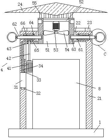
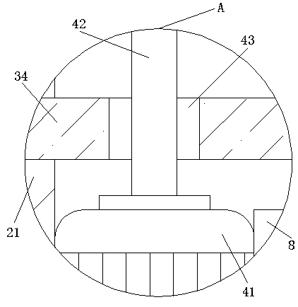
[0025] Such as Figure 1-6 As shown, this specific implementation adopts the following technical solutions:

[0026] A distributed port-shore charging device includes a mounting base 1, a charging pile 8 is fixedly connected to the center of the upper surface of the mounting base 1, and a protection mechanism 2 is installed on the upper surface of the mounting base 1 outside the charging pile 8. A lifting mechanism 3 is installed on the protection mechanism 2, a driving mechanism 4 is installed on the inner side wall of the protection mechanism 2 corresponding to the position of the lifting mechanism 3, and one end of the lifting mechanism 3 is installed with an exhaust mechanism 5, corresponding to the protection of the ventilation mechanism 5 position The mechanism 2 is provided with two positioning mechanisms 6 in a symmetrical shape. The ends of the two positioning mechanisms 6 that are far away from each other penetrate the corresponding side wall of the protection mechanism...


PUM


Abstract

The invention discloses a distributed harbor bank charging device. The device comprises a mounting base, a charging pile is fixedly connected to the center of the upper surface of the mounting base; aprotection mechanism is mounted on the upper surface of the mounting base and located outside the charging pile; a lifting mechanism is mounted on the protection mechanism. When the device is used, the internal charging pile is protected through the protective cover; meanwhile, the protection plate and the air draft sleeve can be driven by the first driving motor to ascend; then the positioning rod is popped into the positioning groove under the action of the spring; fastening an air draft sleeve, at the moment, a second driving motor is started to drive fan blades to rotate to pump out moisture entering the protective cover; and after dehumidification is finished, a first driving motor rotates reversely to drive an air draft sleeve and a protection plate to reset, at the moment, a shielding plate abuts against a rubber sealing ring, ventilation on the protection cover is protected, humid air or seawater is prevented from entering the protection cover through a through hole, and thenthe charging pile in the protection cover is protected.

Description

Technical field [0001] The invention belongs to the technical field of charging devices, and is specifically a distributed port-shore charging device. Background technique [0002] At present, most domestic ports are equipped with charging devices to provide charging devices connected to ships calling at the port to avoid greenhouse gas emissions, noise pollution, and energy consumption caused when ships use diesel and other power generation devices to generate electricity, and can reduce ships’ Pollution caused by the environment. [0003] However, the existing charging devices are all located at the port shore, so the air has a high moisture content and the air is relatively humid. In addition, there are often winds and waves on the port shore that will roll up the water to the shore, which will cause internal damage to the charging device. Corrosion or water ingress greatly reduces the service life of the charging device. For this, it is necessary to design a distributed port-s...

Claims


Application Information

Patent Timeline
IPC IPC(8): H02J7/00B60L53/31
CPCH02J7/0042B60L53/31B60L2200/32Y02T10/70Y02T10/7072Y02T90/12
Inventor 刘展志王文爽刘俊君李腾王汝杰付强王诗旗赵得超陈昭宇郭浩刘文浩孙培博路阳戚冰朱红玲李少梅张坤
Owner 国网山东省电力公司烟台市长岛供电公司
Why Eureka
Try Eureka