Robot motion control method based on electronic cam and control system

A robot motion, electronic cam technology, applied in the direction of program control manipulators, manipulators, manufacturing tools, etc., can solve the problems of limited expansion function and development space, high cost, poor system openness, etc., to improve equipment stability and smoothness. , the effect of reducing equipment procurement and manufacturing costs

Active Publication Date: 2020-04-14
项淮智能科技(长兴)有限公司
View PDF16 Cites 7 Cited by
  • Summary
  • Abstract
  • Description
  • Claims
  • Application Information

AI Technical Summary

Problems solved by technology

[0004] When the robot performs welding, cutting or grinding on the workpiece, the end of the robot is required to move in strict accordance with the planned space trajectory. At present, in the robot motion control, according to the given curve function, the known points on the planned space trajectory are based on Interpolation is carried out to determine the intermedi

Method used


Image

  • Robot motion control method based on electronic cam and control system
  • Robot motion control method based on electronic cam and control system
  • Robot motion control method based on electronic cam and control system

Examples


Embodiment Construction

[0036] The specific implementation manners of the present invention will be further described in detail below in conjunction with the accompanying drawings and embodiments. The following examples are used to illustrate the present invention, but are not intended to limit the scope of the present invention.

[0037] Symbol annotation in the embodiment:

[0038] Z axis: linear joint axis X axis: shoulder joint axis

[0039] Y axis: Elbow joint axis A axis: Wrist joint axis.

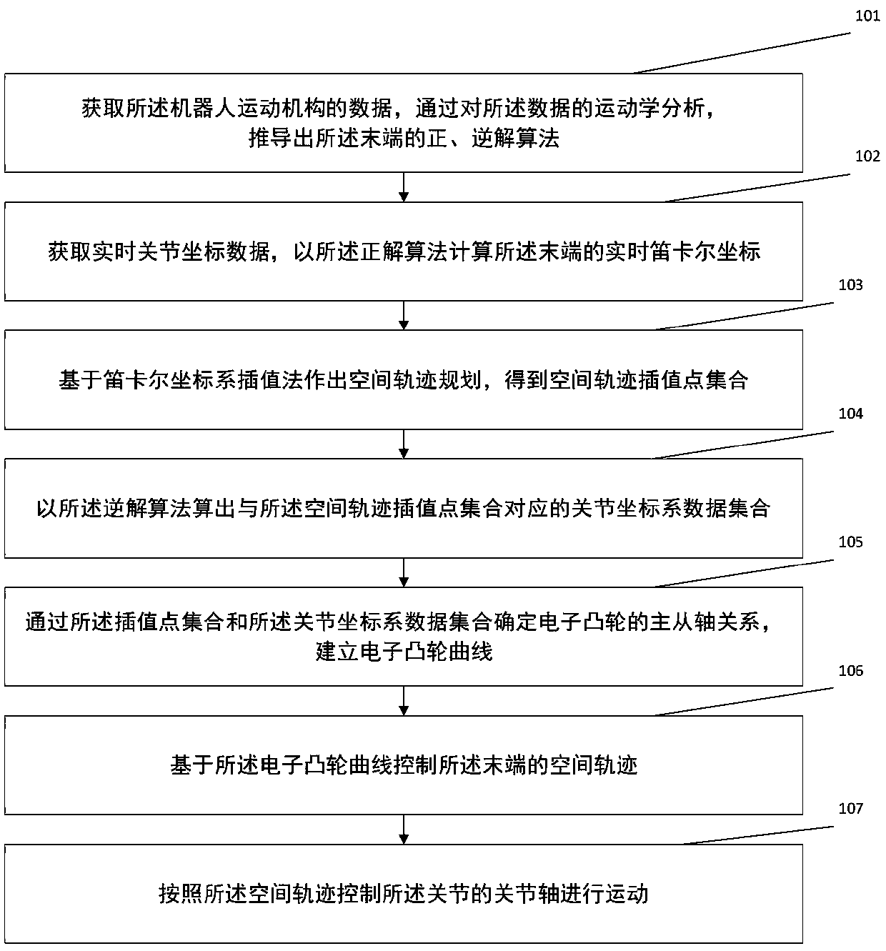
[0040] One aspect of the present invention provides a method for controlling the motion of a robot based on an electronic cam. The robot includes a kinematic mechanism, and the kinematic mechanism includes an end and a joint connected to the end, such as figure 1 As shown, the method includes:

[0041] Step 101: Obtain the data of the robot's kinematic mechanism, and deduce the forward solution algorithm and inverse solution algorithm of the terminal through kinematic analysis of the data;

[0042] Step...


PUM


Abstract

The invention provides a robot motion control method based on an electronic cam and a control system. The method comprises the steps of obtaining data of a robot motion mechanism, and through kinematics analysis of the data, deducing a positive solution algorithm and an inverse solution algorithm of a tail end; obtaining real-time joint coordinate data, and calculating real-time Cartesian coordinates of the tail end with the positive solution algorithm; based on the Cartesian coordinate system, making spatial trajectory planning, and obtaining a space trajectory point set; working out a jointcoordinate system data set corresponding to the space trajectory point set with the inverse solution algorithm; through a point set and the joint coordinate system data set, determining a master and slave shaft relation of the electronic cam, and building an electronic cam curve; based on the electronic cam curve, controlling the spatial trajectory of the tail end; and according to the spatial trajectory, controlling a joint shaft of a joint to move. Robot non-linear motion control is converted into linear motion control, smooth connection between spatial trajectory points can be achieved, andequipment running smoothness and stability can be improved.

Description

technical field [0001] The invention relates to the technical field related to robot control, in particular to an electronic cam-based robot motion control method and control system. [0002] technical background [0003] Trajectory planning refers to the curved trajectory of the end of the robotic arm of the robot, and the curved profile of the displacement, velocity, and acceleration of the end of the robotic arm during motion. The quality of trajectory planning directly affects the work efficiency and motion stability of the robot. [0004] When the robot performs welding, cutting or grinding on the workpiece, the end of the robot is required to move in strict accordance with the planned space trajectory. At present, in the robot motion control, according to the given curve function, the known points on the planned space trajectory are based on Interpolation is carried out to determine the intermediate point and densify the data points. At present, the existing robots can...

Claims


Application Information

Patent Timeline
IPC IPC(8): B25J9/16
CPCB25J9/16B25J9/1628B25J9/1664
Inventor 胡德山李佳鹏龚晓凤韦乐凡
Owner 项淮智能科技(长兴)有限公司
Why Eureka
Try Eureka