Automatic temperature-control and cooling device for lithium battery

A cooling device, lithium battery technology, applied in secondary batteries, battery pack components, circuits, etc., can solve the problems of inability to quickly reduce local temperature, affecting battery use, excessive heat accumulation, etc., to ensure sealing, improve Cooling capacity, the effect of increasing the heat dissipation area

Inactive Publication Date: 2020-04-14
HUBEI UNIV OF TECH
View PDF1 Cites 4 Cited by
  • Summary
  • Abstract
  • Description
  • Claims
  • Application Information

AI Technical Summary

Problems solved by technology

[0004] Based on the technical problem that when the local temperature of the battery is too high, the local temperature cannot be quickly lowered, resulting in excessive heat accumulation and affecting the use of the battery, the present invention proposes an automatic temperature control and cooling device for lithium batteries

Method used


Image

  • Automatic temperature-control and cooling device for lithium battery
  • Automatic temperature-control and cooling device for lithium battery
  • Automatic temperature-control and cooling device for lithium battery

Examples


Embodiment 1

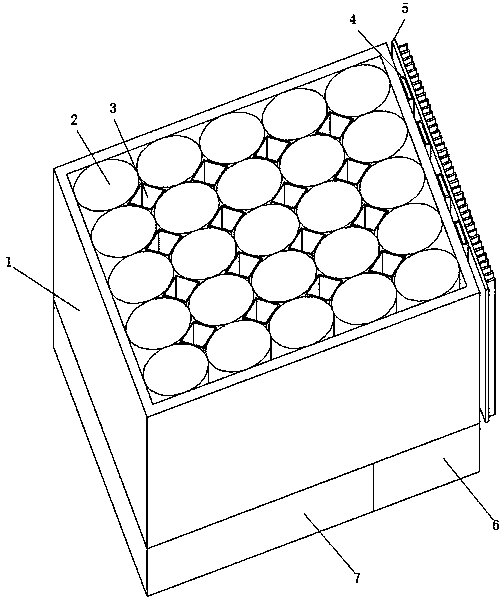
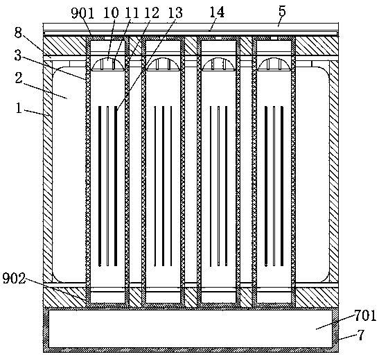
[0029] refer to Figure 1-5 , a lithium battery automatic temperature control and cooling device, including a main body 1, the interior of the main body 1 is provided with a number of batteries 2 and cooling pipes 3, the bottom of the main body 1 is welded with a liquid storage box 7, and one side of the liquid storage box 7 is welded with The fixed box 6 is provided with a driving mechanism inside the fixed box 6, and the top and bottom ends of the cooling pipe 3 are respectively welded with a first connecting pipe 901 and a second connecting pipe 902, and the top of the first connecting pipe 901 is welded with a collecting pipe 14, One end of the collecting pipe 14 is welded with a cooling pipe 4, one side of the cooling pipe 4 and the top of the collecting pipe 14 are welded with a cooling plate 5, and the inside of both sides of the cooling pipe 3 is welded with a fixed block 12, between the two fixed blocks 12 The same elastic plate 10 is welded between them, the top of t...

Embodiment 2

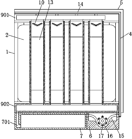
[0039] refer to Image 6 , an automatic temperature control and cooling device for a lithium battery. Compared with Embodiment 1, in this embodiment, in order to increase the heat dissipation performance of the device, a condensing plate 18 is provided inside the liquid storage box 7, and the condensing plate 18 is S-shaped, which can be fully integrated with the The coolant inside the cooling box 7 contacts to reduce the temperature of the coolant. One end of the hose 15 is provided with a temperature control switch, which is electrically connected to the condensation plate 18. When the coolant inside the hose 15 has been cooled When the temperature is too high, the temperature control switch is connected to the condensing plate 18, so that the temperature of the cooling liquid inside the liquid storage box 7 is reduced, and the heat dissipation performance is enhanced.

[0040] When in use, when the motor drives the rotating wheel 16 to rotate, the roller 17 will rotate acco...


PUM


Abstract

The invention belongs to the technical field of electrical equipment, and relates to an automatic temperature-control and cooling device, when the local temperature of a battery is too high, the use of battery is influenced due to excessive heat accumulation caused by the fact that the local temperature cannot be quickly reduced, the invention provides the following scheme that the device comprises a main body, a plurality of batteries and cooling pipes are arranged in the main body, a liquid storage box is welded at the bottom end of the main body, a fixed box is welded on one side of the liquid storage box, and a driving mechanism is arranged in the fixed box. In the present invention, when the local battery temperature is too high, the temperature of the cooling liquid in a cooling pipenear the battery rises; a bimetallic strip in the cooling pipe is bent; the bimetallic strip enables the V-shaped elastic sheet to be bent, an internal diameter of the cooling pipe is increased, theflow rate of the cooling liquid is accelerated, the temperature of the battery with local temperature rise is quickly reduced, the flow rate of the cooling liquid with lower temperature is transferedto the part with higher temperature, the temperature is quickly reduced, and the power of the device is not required to be increased.

Description

technical field [0001] The invention relates to the technical field of electrical equipment, in particular to an automatic temperature control and cooling device for a lithium battery. Background technique [0002] Lithium battery is a reusable rechargeable battery, but during use, the battery is prone to heat, which not only affects the performance of the battery, but also causes a fire hazard when the heat is severe, and the heat is distributed unevenly, and the temperature in some places is too high. High, resulting in excessive heat accumulation, affecting the use of the battery. [0003] After searching, the Chinese patent application number is CN201621239772.1, which discloses a dual-channel battery pack air cooling structure, including a housing, a battery pack, a first collector plate and a second collector plate built in the housing, the first The first and second current collectors are fixed at both ends of the battery pack; the front side of the housing is distri...

Claims


Application Information

Patent Timeline
Patent Type & Authority Applications(China)
IPC IPC(8): H01M10/613H01M10/617H01M10/643H01M10/6551H01M10/6554H01M10/6557H01M10/6568H01M2/10
CPCH01M10/613H01M10/617H01M10/643H01M10/6551H01M10/6554H01M10/6557H01M10/6568H01M50/20Y02E60/10
Inventor 汪繁荣向堃张冉王达王慧
Owner HUBEI UNIV OF TECH
Why Eureka
Try Eureka