Automatic deoiling device for bolt deoiling

A deoiling device and deoiling technology, applied to centrifuges and other directions, can solve the problems of time-consuming and laborious, difficult to remove bolts, and reduce the service life of deoiling components, so as to reduce noise and facilitate unloading

Inactive Publication Date: 2020-04-17
ZHEJIANG COWIN FASTECH
View PDF7 Cites 2 Cited by
  • Summary
  • Abstract
  • Description
  • Claims
  • Application Information

AI Technical Summary

Problems solved by technology

This kind of centrifugal deoiling machine is generally vertical. A deoiling cylinder is installed on the upper part of a frame, and then the cold forged product with oil is put into the oil filter, and then the motor is started to make the oil filter rotate at a high speed. Deoiling, stop the motor after deoiling is completed, but it is difficult to take out the bolts after deoiling, which is time-consuming and laborious, and the existing vertical centrifugal deoiling machine does not have a shock absorber, and the deoiling machine is prone to vibration when it starts and stops , so that the deoiling component rotates in a vibrating state, which not only reduces the service life of the deoiling component, but also brings the noise of rotation vibration

Method used


Image

  • Automatic deoiling device for bolt deoiling
  • Automatic deoiling device for bolt deoiling
  • Automatic deoiling device for bolt deoiling

Examples


Embodiment 1

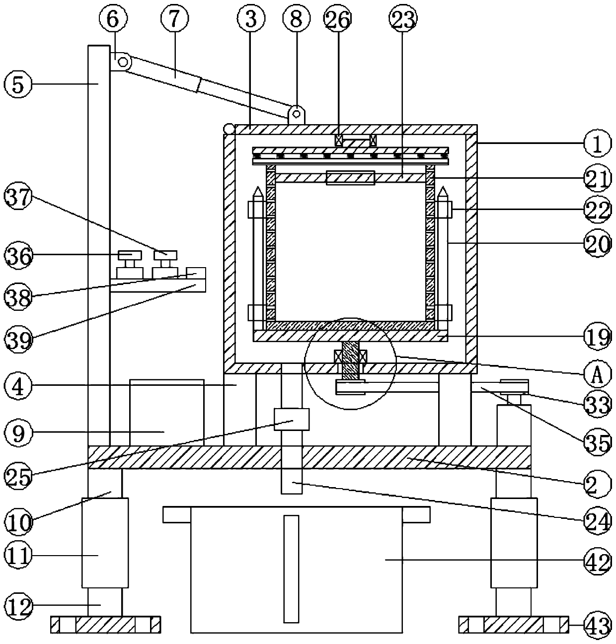
[0036] See Figure 1-6 , According to an embodiment of the present invention, an automatic de-oiling device for bolt de-oiling includes a housing 1 and a workbench 2. The housing 1 has a cylindrical structure, and the housing 1 is movably set on a rotating shaft. There is a cover plate 3, a number of four fixing posts 4 are fixed under the housing 1, and the fixing posts 4 are all fixed on the worktable 2, and one end of the worktable 2 is fixed with a side post 5, The upper end of the side column 5 is fixedly provided with a first hinge base 6, an electric telescopic rod 7 is hinged in the first hinge base 6, and a second hinge base 8 is fixed on the cover plate 3. The electric telescopic rod 7 One end far away from the first hinge base 6 is hinged with the second hinge base 8, the inner wall of the middle part of the side column 5 is provided with a control device, and a PLC controller 9 is fixed on the workbench 2, and the workbench A first sliding rod 10 is fixed under the...

Embodiment 2

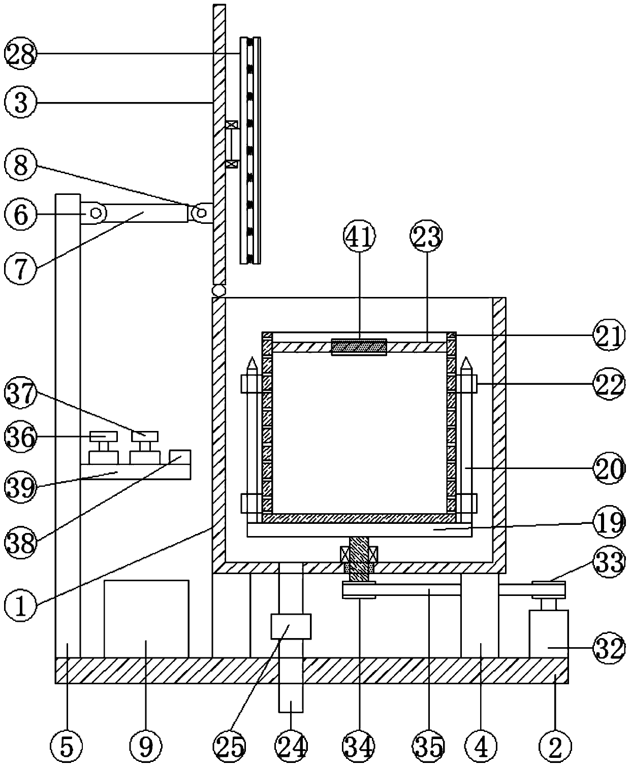
[0039] See figure 1 , 5 And 6, for the energy absorbing material 16, the energy absorbing material 16 is ACF artificial cartilage foam; for the pressurizing device, the pressurizing device includes a second bearing 26, and the second bearing 26 is internally fixed There is a second transmission shaft 27, a first circular plate 28 is fixed under the second transmission shaft 27, and a second circular plate 30 is connected under the first circular plate 28 through a plurality of first springs 29. A rubber pad 31 is fixed under the circular plate 30; for the driving device, the driving device includes a motor 32, a first pulley 33, a second pulley 34, and a V-belt 35. The motor 32 is fixed on the workbench 2 Above, the outer wall of the rotating shaft of the motor 32 is fixedly sleeved with a first pulley 33, and the outer wall of the lower end of the first drive shaft 18 is fixedly sleeved with a second pulley 34, the first pulley 33 and the second pulley 34 It is driven by a V-b...

Embodiment 3

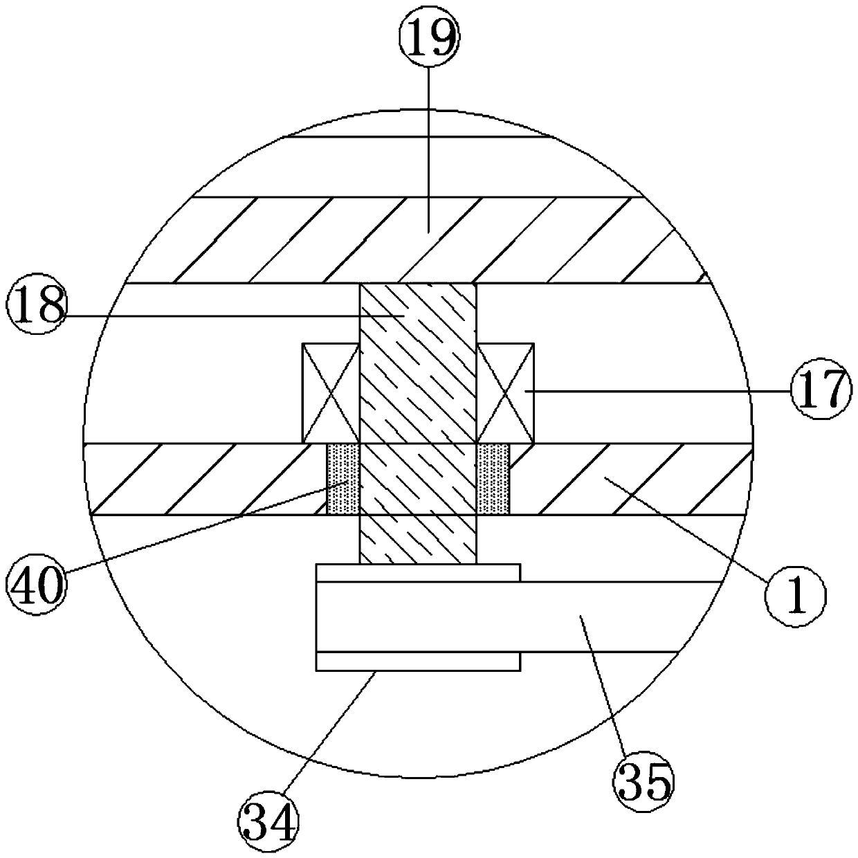
[0042] See figure 1 with 2 For the control device, the control device includes a timing knob 36, a speed control knob 37, a cover opening button 38, and a mounting plate 39. The timing knob 36, the speed control knob 37 and the cover opening button 38 are all Fixed on the mounting plate 39, the mounting plate 39 is fixed on the inner wall of the middle part of the side column 5, the timing knob 36, the speed control knob 37 and the opening button 38 are all connected to the PLC controller 9 electrical connection; for the first transmission shaft 18, the outer wall of the junction between the first transmission shaft 18 and the housing 1 is sleeved with a rotary shaft sealing ring 40, and the rotary shaft sealing ring 40 is fixedly embedded in The bottom of the housing 1.

[0043] Through the above-mentioned solution of the present invention, the timing knob 36 can be used to turn on the motor 32 and control the working time of the motor 32, the speed of the motor 32 can be adjust...


PUM


Abstract

The invention discloses an automatic deoiling device for bolt deoiling. The automatic deoiling device comprises a shell and a workbench; the shell is of a cylindrical structure; a cover plate is movably arranged on the shell through a rotating shaft; four fixed columns are fixedly arranged below the shell; all the fixed columns are fixed to the workbench, a side column is fixedly arranged at one end of the workbench; a first hinged support is fixedly arranged at the upper end of the side column, an electric telescopic rod is hinged to the interior of the first hinged support, a second hinged support is fixedly arranged on the cover plate, and one end, away from the first hinged support, of the electric telescopic rod is hinged to the second hinged support. The automatic deoiling device hasthe beneficial effects that a centrifugal barrel can be taken out of the shell, so that deoiled bolts can be directly poured out, blanking can be facilitated, the damping effect can be achieved through cooperation of a second spring and an energy absorption material, the damping protection effect on the deoiling assembly can be achieved, and noise generated by vibration can be reduced.

Description

Technical field [0001] The invention relates to the technical field of bolt deoiling, and in particular to an automatic deoiling device for bolt deoiling. Background technique [0002] Bolts: mechanical parts, cylindrical threaded fasteners with nuts. A type of fastener consisting of a head and a screw (cylinder with external threads), which needs to be matched with a nut to fasten and connect two parts with through holes. The cold heading machine is the main equipment for mass production of bolts. During the production and processing of cold forging equipment, the cold heading products need to be cooled. Based on the requirements for the reuse of cooling oil and the cleanliness of cold heading products, the bolts need to be deoiled. [0003] The current deoiling method in the production process is to set up a centrifugal deoiling machine separately. This kind of centrifugal de-oiling machine is generally vertical. A de-oiling cylinder is installed on the upper part of a frame, ...

Claims


Application Information

Patent Timeline
Patent Type & Authority Applications(China)
IPC IPC(8): B04B7/00B04B15/00B04B9/02B04B13/00
CPCB04B7/00B04B9/02B04B13/00B04B15/00
Inventor 杨荣德
Owner ZHEJIANG COWIN FASTECH
Why Eureka
Try Eureka