Thick steel plate double-sided laser-MAG composite large root face backing welding method

A hybrid welding and laser technology, applied in laser welding equipment, welding equipment, metal processing equipment, etc., can solve problems such as air holes, and achieve the effect of improving welding quality and efficiency

Pending Publication Date: 2020-04-17
渤海造船厂集团有限公司
View PDF13 Cites 1 Cited by
  • Summary
  • Abstract
  • Description
  • Claims
  • Application Information

AI Technical Summary

Problems solved by technology

[0004] In order to be able to solve the defect of air holes at the root of thick steel plate with large blunt edge bottoming welding, the present invention proposes a double-sided laser-MAG composite large blunt edge bottoming welding method for thick steel plate
This method adopts double-sided laser-MAG composite bottoming welding, and uses high-power laser-MAG composite welding on the first welding surface to realize d

Method used


Image

  • Thick steel plate double-sided laser-MAG composite large root face backing welding method
  • Thick steel plate double-sided laser-MAG composite large root face backing welding method

Examples


Embodiment 1

[0019] Taking the SA-738Gr.B steel butt horizontal welding process with a length of 500mm and a plate thickness of 80mm as an example, the welding implementation steps and process are described in detail.

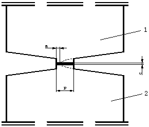
[0020] (1) Machining the first workpiece to be welded 1 and the second workpiece 2 to be welded into double U-shaped welding grooves with blunt edges, the thickness p of the blunt edges without penetration is 7mm;

[0021] (2) Assemble the first workpiece to be welded and the second workpiece to be welded, the assembly gap c is 0~0.3mm;

[0022] (3) Remove oxide scale, oil stains, rust, moisture and other dirt from the groove and its surroundings before welding;

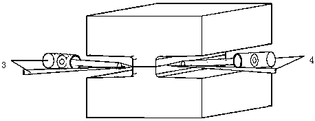
[0023] (4) The front laser-MAG composite welding gun 3 and the rear laser-MAG composite welding gun 4 are used for bottom welding with φ1.2mm welding wire on both sides of the welding groove. The front laser-MAG composite welding gun starts arcing at an interval of 8s, and the rear laser- MAG composite welding torch start...

Embodiment 2

[0025] Taking the A514Gr.Q steel butt horizontal welding process with a length of 500mm and a plate thickness of 114mm as an example, the welding implementation steps and processes are described in detail.

[0026] (1) Machining the first workpiece to be welded and the second workpiece to be welded into double V-shaped welding grooves with blunt edges, the thickness p of the blunt edges without penetration is 9mm;

[0027] (2) Assemble the first workpiece to be welded and the second workpiece to be welded, and the assembly gap c is 0~0.2mm;

[0028] (3) Remove oxide scale, oil stains, rust, water and other dirt from the groove and its surroundings before welding;

[0029] (4) Use the front laser-MAG composite welding torch and the rear laser-MAG composite welding torch to use φ1.2mm welding wire for bottom welding on both sides of the welding groove. The front laser-MAG composite welding torch starts arcing at an interval of 30s, and the rear laser-MAG composite welding torch The weld...


PUM


Abstract

The invention provides a thick steel plate double-sided laser-MAG composite large root face backing welding method. The thick steel plate double-sided laser-MAG composite large root face backing welding method includes the steps that a first workpiece to be welded and a second workpiece to be welded are machined into a double-U-shaped or double-V-shaped welding groove with root faces; the first workpiece to be welded and the second workpiece to be welded are assembled; oxide skin, oil dirt, rust, moisture and other dirt around the groove are removed before welding; and a front laser-MAG composite welding gun and a rear laser-MAG composite welding gun are used for backing welding on the two sides of the welding groove with a welding wire being Phi1.0-Phi1.6mm. According to the thick steel plate double-sided laser-MAG composite large root face backing welding method, the problem of airpoles in one-time complete penetration forming of high-strength steel thick plate large root face laser-MAG composite backing welding is solved, and the welding quality and efficiency of the high-strength steel plate and the high-strength steel are improved, and the method application is suitable for the thick steel plate double-sided laser-MAG composite large root face backing welding.

Description

Technical field [0001] The invention relates to the technical field of laser welding, in particular to a method for bottom welding of steel thick plates with double-sided laser-MAG composite large blunt edges. Background technique [0002] At present, the commonly used welding method for welding high-strength steel thick plates in nuclear power and marine engineering is SMAW or MAG welding. After welding one side of the weld, use carbon arc gouging to clean the root and then weld the other side of the weld. The disadvantage is Large mouth angle, large amount of filler metal, low welding efficiency, large welding deformation, and poor welding quality. [0003] Laser-arc hybrid welding has attracted wide attention due to its high efficiency, high adaptability, large penetration depth, and low heat input. However, when this method is used for bottoming welding of thick plates of high-strength steel with large blunt edges, if the penetration forming is performed once, the laser keyhol...

Claims


Application Information

Patent Timeline
IPC IPC(8): B23K26/348B23K26/14B23K26/70
CPCB23K26/14B23K26/348B23K26/702
Inventor 李洋刘殿宝吴满鹏赵俊凯陈治坤魏强朱云龙高恩双
Owner 渤海造船厂集团有限公司
Why Eureka
Try Eureka