Eureka AIR delivers breakthrough ideas for toughest innovation challenges, trusted by R&D personnel around the world.

Shaping tool and C/SiC composite structural part forming method adopting shaping tool

A molding method and technology for structural parts, applied in the field of C/SiC composite material preform molding tooling, can solve the problems of low assembly accuracy, narrow local space, difficult operation, etc., achieve convenient processing and transportation, large adjustment space, and improve the overall the effect of strength

Active Publication Date: 2020-04-17
XIAN XINGUI CERAMIC COMPOSITE MATERIAL CO LTD
View PDF6 Cites 1 Cited by
  • Summary
  • Abstract
  • Description
  • Claims
  • Application Information

AI Technical Summary

Problems solved by technology

[0003] The main purpose of the present invention is to solve the existing technical problems of narrow local space, difficult operation and low assembly precision in the existing C / SiC composite structural parts formed by single parts and then riveted and welded. And the forming method of C / SiC composite material structural parts using shaping tooling

Method used


Image

  • Shaping tool and C/SiC composite structural part forming method adopting shaping tool
  • Shaping tool and C/SiC composite structural part forming method adopting shaping tool
  • Shaping tool and C/SiC composite structural part forming method adopting shaping tool

Examples


Embodiment 1

[0057] The method for forming a C / SiC composite structural part using the above-mentioned shaping tooling includes the following steps:

[0058] Step 1, box type 5 with punching holes

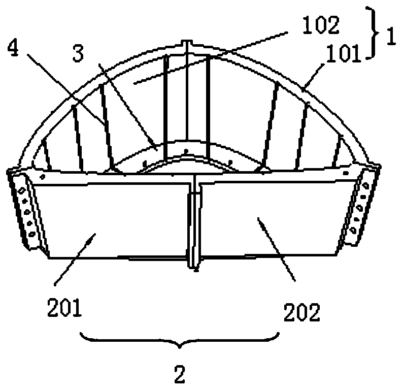
[0059] Take a plurality of box-shaped parts 5 with upper openings, the outer dimensions of the box-shaped parts 5 are adapted to the shaped top plate 1 or shaped bottom plate 2 between adjacent limiting grooves 4, and there is a connection relationship between each box-shaped part 5 The side walls of each are equipped with perforated holes, the hole diameter is 3mm, and the hole center distance is 6mm;

[0060] Step 2, the outer wall of the box-shaped part 5 is wrapped with carbon fiber cloth

[0061] Wrap multiple layers of carbon fiber cloth on the outer wall of each box-shaped part 5, and the edge of the carbon-fiber cloth is 5mm higher than the upper surface of the box-shaped part 5;

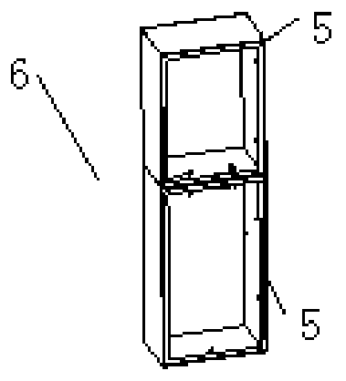
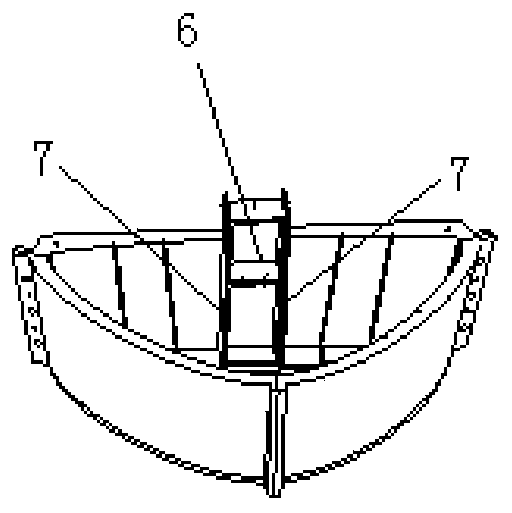
[0062] Step 3, Assembling Box Components 6

[0063] Such as figure 2 , place two box-shaped parts 5 i...

Embodiment 2

[0082] The method for forming a C / SiC composite structural part using the aforementioned sizing tooling comprises the following steps:

[0083] Step 1, box type 5 with punching holes

[0084] Take a plurality of box-shaped parts 5 with upper openings, the outer dimensions of the box-shaped parts 5 are adapted to the shaped top plate 1 or shaped bottom plate 2 between adjacent limiting grooves 4, and there is a connection relationship between each box-shaped part 5 The side walls of each are equipped with perforated holes, the hole diameter is 5mm, and the hole center distance is 9mm;

[0085] Step 2, the outer wall of the box-shaped part 5 is wrapped with carbon fiber cloth

[0086] Wrap multiple layers of carbon fiber cloth on the outer wall of each box-shaped part 5, and the edge of the carbon-fiber cloth is 8mm higher than the upper surface of the box-shaped part 5;

[0087] Step 3, Assembling Box Components 6

[0088] Place at least two box-shaped parts 5 in the same di...

Embodiment 3

[0107] The method for forming a C / SiC composite structural part using the above-mentioned shaping tooling includes the following steps:

[0108] Step 1, box type 5 with punching holes

[0109] Take a plurality of box-shaped parts 5 with upper openings, and punch holes in each side wall of each box-shaped part 5 with a connection relationship, the hole diameter is 6mm, and the distance between the holes is 10mm;

[0110] Step 2, the outer wall of the box-shaped part 5 is wrapped with carbon fiber cloth

[0111] Wrap multiple layers of carbon fiber cloth on the outer wall of each box-shaped part 5, and the edge of the carbon-fiber cloth is 10mm higher than the upper surface of the box-shaped part 5;

[0112] Step 3, Assembling Box Components 6

[0113] Place at least two box-shaped parts 5 in the same direction, and fix the adjacent surfaces of every two adjacent box-shaped parts 5 to form a box-shaped assembly 6; the height of the box-shaped assembly 6 is greater than the hei...


PUM


Abstract

The invention belongs to C / SiC composite preform forming tools and methods, and provides a shaping tool and a C / SiC composite structural part forming method adopting the shaping tool in order to solvethe problems that the forming process that after single parts are formed, then rivet welding and assembling are carried out is adopted by an existing C / SiC composite structural part, during assembling, the local space is narrow, operation is difficult, and the assembling precision is low. The shaping tool comprises an arch-shaped shaping top plate, and the shaping top plate is mounted on a shaping bottom plate. The back sides of the shaping top plate and the shaping bottom plate are bent inwards to form shaping supporting edges, multiple limiting grooves are formed in the shaping top plate and the shaping bottom plate, and limiting slabs are clamped in the limiting grooves. According to the forming method, shaping supporting is carried out through a box-shaped assembly, the thickness of carbon fiber cloth of the box-shaped assembly is adjusted through the limiting grooves and the limiting slabs, and the smoothness and thickness consistency of the carbon cloth is guaranteed. Laying whole cloth is subjected to flanging treatment, a flanged and cut opening is reinforced, and therefore the overall strength of a composite is guaranteed. A C / SiC composite structural part is firstly shaped and then deposited.

Description

technical field [0001] The invention belongs to a C / SiC composite material prefabricated body molding tool and method, in particular to a shaping tool and a C / SiC composite material structural member molding method using the shaping tool. Background technique [0002] Cabin-like C / SiC composite structural parts generally have large dimensions, a large number of grids, and complex curved surfaces. The existing forming process is generally to split a large structural part into multiple small structural parts, first form a single small part and then rivet and weld the assembly. When assembled by conventional rivet welding process, there are often problems of narrow local space, difficult operation and low assembly accuracy. And in the rivet welding process, the pores between the grids are relatively large. Contents of the invention [0003] The main purpose of the present invention is to solve the existing technical problems of narrow local space, difficult operation and lo...

Claims


Application Information

Patent Timeline
Patent Type & Authority Applications(China)
IPC IPC(8): B29B15/08C04B35/80
CPCB29B15/08
Inventor 李仁意张倩苏海龙张建平康志杰李建章成来飞
Owner XIAN XINGUI CERAMIC COMPOSITE MATERIAL CO LTD
Why Eureka
Eureka Blog
Learn More