Reactor capable of stratification and near true plug-flow conditions and its treatment method

A reactor, stratified flow technology, applied in chemical instruments and methods, biological water/sewage treatment, water/sludge/sewage treatment, etc., can solve the problems of long diffusion length and low mixing efficiency, achieve volume reduction, Uniform distribution guarantees the effect of shortening the mass transfer distance

Active Publication Date: 2022-03-25
柏中环境科技(上海)股份有限公司 +1
View PDF0 Cites 1 Cited by
  • Summary
  • Abstract
  • Description
  • Claims
  • Application Information

AI Technical Summary

Problems solved by technology

Disadvantages of MBBR systems are their low mixing efficiency and long diffusion lengths

Method used


Image

  • Reactor capable of stratification and near true plug-flow conditions and its treatment method
  • Reactor capable of stratification and near true plug-flow conditions and its treatment method
  • Reactor capable of stratification and near true plug-flow conditions and its treatment method

Examples


Embodiment 1

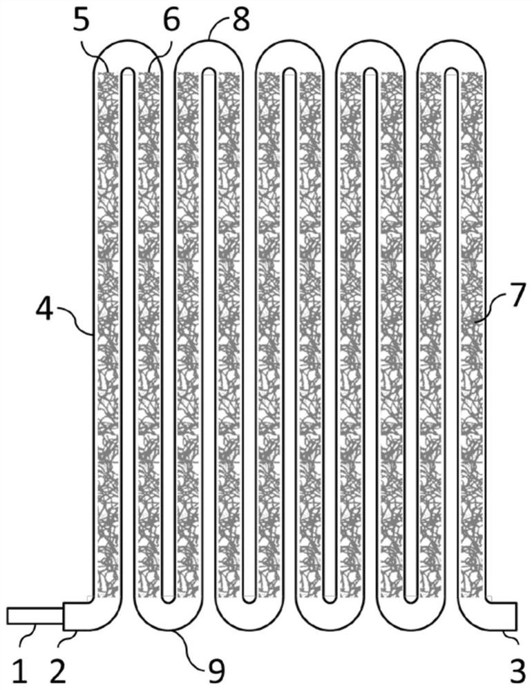
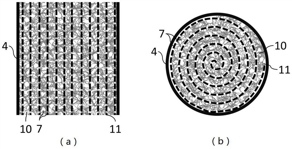
[0047] Such as figure 1 As shown, a plug-flow reactor includes a reactor body, the reactor body 4 is provided with a reactor inlet 2 and a reactor outlet 3, and the reactor inlet 2 communicates with a water inlet pipe 1 . The reactor body 4 is filled with a composite biological carrier 7, the composite biological carrier 7 includes at least two biological carrier layers, the composite biological carrier 7 includes a main biological carrier 10 and a secondary biological carrier 11 connected to each other, the The porosity of the main biological carrier 10 is higher than that of the secondary biological carrier 11 . The reactor body 4 includes an upflow section 5 and a downflow section 6 interconnected in sequence, and the flow direction of the fluid in the upflow section 5 and the downflow section 6 is perpendicular to the horizontal plane. The raw sewage enters the reactor body 4 at the reactor inlet 2 through the water inlet pipe 1 , and the treated wastewater is discharged ...

Embodiment 2

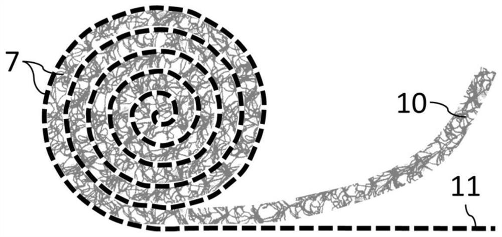
[0061] On the basis of Example 1, such as Figure 4 As shown, the high-porosity main biological carrier 10 and the low-porosity secondary biological carrier 11 can be combined and used in multiple layers. That is, at least two main biological carriers 10 and at least two secondary biological carriers 11 can be used. for example, Figure 4 A composite biocarrier 7 is shown, comprising two primary biocarrier layers, a first primary biocarrier layer 12 and a second primary biocarrier layer 13, and two secondary biocarrier layers, a first secondary biocarrier layer layer 14 and second by-biological carrier layer 15.

[0062] The second main biological carrier layer 13, the second secondary biological carrier layer 15, the first main biological carrier layer 12, and the first secondary biological carrier layer 14 are stacked together successively and curled into an Archimedes spiral, because the secondary biological carrier The layer thickness is very small, the pitch of the spi...

Embodiment 3

[0067] A plug-flow biological reaction treatment method, the liquid to be treated is processed by the plug-flow reactor as described in the above embodiment 1 or embodiment 2, and the liquid to be treated contains one or more dissolved or suspended substances . The superficial velocity v of the liquid in the reactor body pf pf = 0.05-0.15 m / s. The lower flow rate of the control liquid induces less turbulence resulting in less head loss and thus lower energy consumption.

[0068] Further, the composite biological carrier comprises at least one main biological carrier layer and at least one secondary biological carrier layer, and the liquid is divided into multiple layers between the secondary biological carrier layers to realize laminar flow.


PUM


Abstract

The present invention provides a reactor capable of realizing stratification and close to real plug-flow conditions and a treatment method thereof. The reactor includes a reactor body filled with a composite biological carrier, and the composite biological carrier is a plurality of Layer structure, the composite biological carrier is provided with layered channels along the flow direction; the composite biological carrier includes at least one layer of main biological carrier and at least one layer of secondary biological carrier, and the porosity of the main biological carrier is higher than that of the secondary biological carrier. By adopting the technical scheme of the present invention, the fluid can reach a real pushing flow state in the biofilm reactor, and the fluid realizes a layered flow system in the narrow flow channel, and the waste water and the biofilm attached to the fixed biological carrier The maximum distance between convective and diffusive mass transfer is drastically reduced, and the overall reactor volume can typically be reduced by 25% compared to conventional systems. Moreover, due to the absence of anti-mixing and short flow, the system runs more stably and has higher processing efficiency.

Description

technical field [0001] The invention relates to the technical field of waste water treatment, in particular to a reactor capable of realizing stratification and close to real plug-flow conditions and a treatment method thereof. Background technique [0002] In the prior art, in the wastewater biological treatment process, the organic components and nutrients dissolved or suspended in the wastewater are generally removed by microorganisms, especially bacteria. Here, the microorganisms can be suspended in the water body (as a mixed solution) or immobilized in a biofilm on the surface of the carrier material. [0003] Organic matter and nutrients in the liquid must come into contact with microorganisms before they can be removed. In wastewater biological treatment systems, two different mass transfer mechanisms can be observed, namely convective and diffusive mass transfer. Among them, convective mass transfer needs to be realized under intense mixing conditions, while diffus...

Claims


Application Information

Patent Timeline
Patent Type & Authority Patents(China)
IPC IPC(8): C02F3/00
CPCC02F3/00
Inventor 付思特
Owner 柏中环境科技(上海)股份有限公司
Why Eureka
Try Eureka