Carburization heat treatment control method for Spiral bevel gear

A technology of spiral bevel gear and control method, applied in heat treatment furnaces, heat treatment equipment, manufacturing tools, etc., can solve problems such as processing influence, immature carburized layer depth, influence product quality, etc., and achieve reasonable process technology and controlled infiltration. Depth of carbon layer and effect of quenching deformation

Active Publication Date: 2020-04-17
ZHONGNAN TRANSMISSION MACHINERY FACTORY CHANGSHAAVIATION IND
View PDF3 Cites 1 Cited by
  • Summary
  • Abstract
  • Description
  • Claims
  • Application Information

AI Technical Summary

Problems solved by technology

At present, domestic research on the manufacture of this material is still in its infancy and experience accumulation stage, and the precise control technology for the depth of the carburized layer is not yet mature. For parts with different carburized depths in different parts, the process method of secondary carburizing superposition is often used. However, repeated heating aggravates the deformation of the parts, especially for thin-walled cylindrical parts, the severe deformation has a great impact on the subsequent processing
If press quenching is used to control deformation, the quenching temperature of this material will be as high as 1060-1070°C, which will lead to difficult quenching operation and seriously affect product quality
Aviation products involve a spiral bevel gear part. Its structure is a thin-walled cylindrical gear part. The carburized depth of the tooth is required to be 1.25-1.45mm, the hardness of the carburized surface of the tooth is 63-67HRC, and the depth of the carburized layer in the inner hole is 0.8~1.0mm, the hardness of the carburized surface of the inner hole is ≥60HRC, and the ellipticity of the inner hole after quenching is ≤0.10. The traditional superimposed carburizing and repeated heating will cause quenching deformation, and the spiral bevel gear that meets the above requirements cannot be obtained.

Method used


Image

  • Carburization heat treatment control method for Spiral bevel gear

Examples


Embodiment 1

[0031] An aviation product spiral bevel gear requires a carburized depth of 1.25-1.45mm, a carburized surface hardness of 63-67HRC, a carburized layer depth of 0.8-1.0mm, and a carburized surface hardness of ≥60HRC. , After quenching, the ellipticity of the inner hole is ≤0.10.

[0032] The raw material of the spiral bevel gear in this embodiment is 15Cr14Co12Mo5Ni steel.

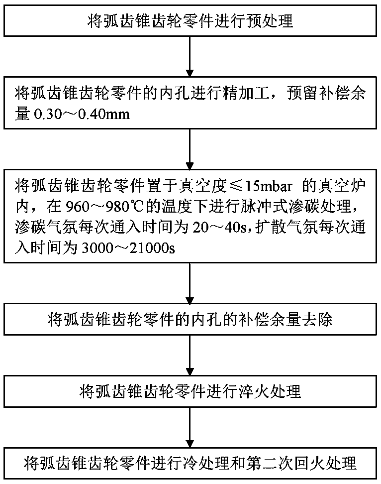
[0033] Such as figure 1 As shown, the carburizing heat treatment control method of a spiral bevel gear in this embodiment includes the following steps:

[0034] (1) The tooth part of the spiral bevel gear part has been processed before copper plating, and the inner hole has been processed to a predetermined size for subsequent copper plating.

[0035] (2) The surface of the spiral bevel gear parts is protected by copper plating except for the teeth, and the thickness of the copper layer is 0.03-0.05mm (0.035mm in this embodiment).

[0036] (3) Finishing the carburized area of ​​the inner hole of the spir...


PUM

PropertyMeasurementUnit
depthaaaaaaaaaa
thicknessaaaaaaaaaa
depthaaaaaaaaaa

Abstract

The invention discloses a carburization heat treatment control method for a spiral bevel gear. The carburization heat treatment control method includes the following steps that pretreatment is conducted on the spiral bevel gear part; finish machining is conducted on an inner hole of the spiral bevel gear part, and the compensation allowance of 0.30 mm-0.40 mm is reserved; the spiral bevel gear isput into a vacuum furnace with the vacuum degree being smaller than or equal to 15 mbar, impulse type carburization treatment is conducted under the temperature of 960 DEG C to 980 DEG C, the chargingtime of the carburization atmosphere of each time is 20 s to 40 s, and the charging time of the diffusion atmosphere of each time is 3000 s to 21000 s; first-time tempering treatment is conducted onthe spiral bevel gear part; the compensation allowance of the inner hole of the spiral bevel gear part is removed; and quenching treatment, cold treatment and second-time tempering treatment are conducted on the spiral bevel gear part. By means of the carburization heat treatment control method for the spiral bevel gear, different carburization layer depth requirements and deformation requirementsexist for different parts of the spiral bevel gear.

Description

technical field [0001] The invention relates to the field of heat treatment of low-carbon high-alloy steel, in particular to a carburizing heat treatment control method of a spiral bevel gear. Background technique [0002] 15Cr14Co12Mo5Ni steel is a low-carbon high-alloy steel. It is a new type of carburized gear steel. After quenching, the surface can obtain high hardness and has excellent strength and toughness. At present, domestic research on the manufacture of this material is still in its infancy and experience accumulation stage, and the precise control technology for the depth of the carburized layer is not yet mature. For parts with different carburized depths in different parts, the process method of secondary carburizing superposition is often used. However, repeated heating aggravates the deformation of the parts, especially for thin-walled cylindrical parts, the severe deformation has a great impact on the subsequent processing. If press quenching is used to co...

Claims


Application Information

Patent Timeline
Patent Type & Authority Applications(China)
IPC IPC(8): C23C8/22C23C8/80C23C8/02C21D1/18C21D6/00C21D9/32
CPCC23C8/22C23C8/80C23C8/02C21D1/18C21D6/004C21D6/007C21D9/32Y02P10/20
Inventor 王广超吴平汤宁照刘龙凯唐梦兰
Owner ZHONGNAN TRANSMISSION MACHINERY FACTORY CHANGSHAAVIATION IND
Why Eureka
Try Eureka