Jet flow type electrochemical deposition device

A deposition equipment, electrochemical technology, applied in the direction of electrodes, electrolytic process, electrolytic components, etc., can solve the problems of excessive consumption of additives, contamination of ion membranes, etc., and achieve the effect of avoiding oxidation

Inactive Publication Date: 2020-04-17
ANHUI HONGSHI AUTOMATION EQUIP CO LTD
View PDF7 Cites 2 Cited by
  • Summary
  • Abstract
  • Description
  • Claims
  • Application Information

AI Technical Summary

Problems solved by technology

[0004] The object of the present invention is to provide a jet-flow electrochemical deposition equipment to solve the following technical problems: (1) One or more jet flow mechanisms, cathodes, and anodes can be arranged side by side in the electroplating tank to meet the requirements for one or more substrates. The electrolysis at the bottom, through the design of the jet flow mechanism, the diaphragm separates the catholyte in the cathode chamber and the anolyte in the anode chamber. During the electrolysis process, there is no need to add additives to the solution in the anode chamber. The distribution of the jet holes can be adjusted according to different linings. The shape of the bottom can be adjusted to meet the electroplating effect of different shapes of objects to be plated. T...

Method used


Image

  • Jet flow type electrochemical deposition device
  • Jet flow type electrochemical deposition device
  • Jet flow type electrochemical deposition device

Examples


Embodiment 1

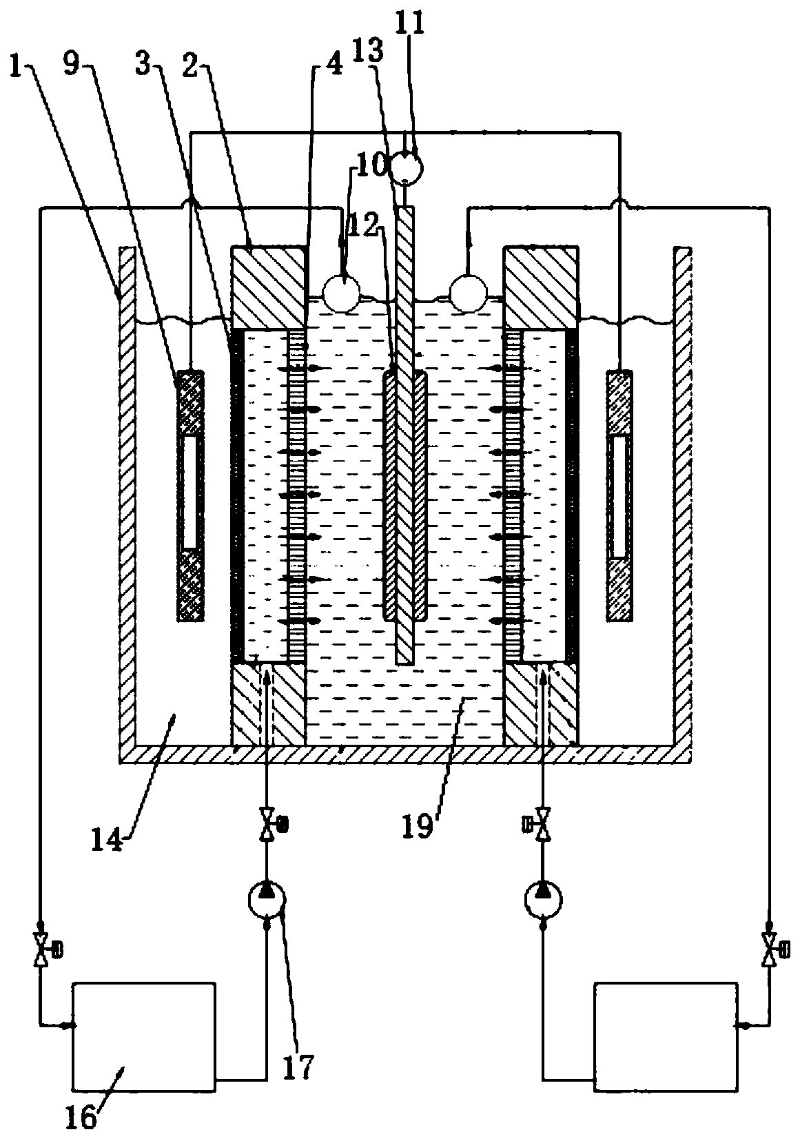
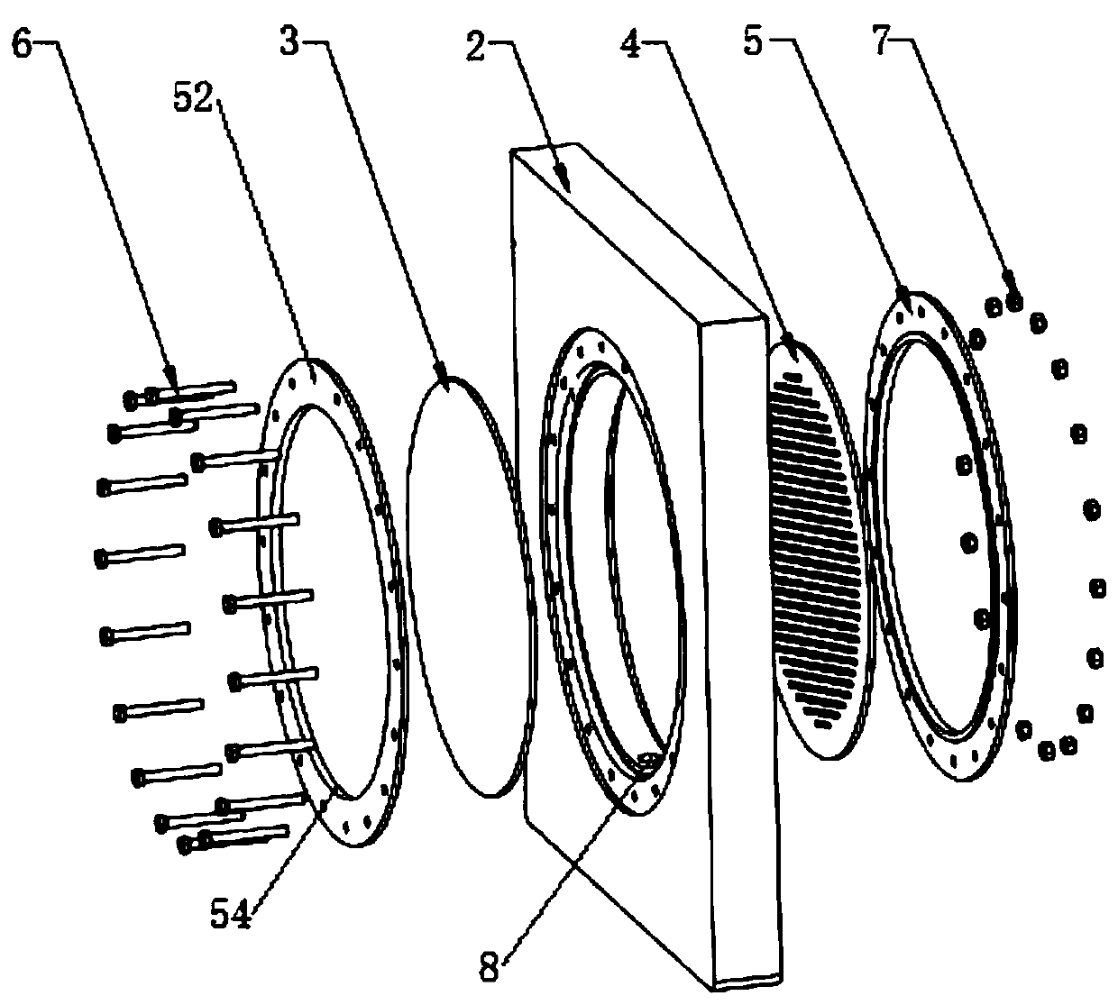
[0030] refer to figure 1 , 3 , 4, a kind of jet-flow electrochemical deposition equipment, comprise electroplating tank 1, substrate holder 13 is installed in the electroplating tank 1 tank, substrate holder 13 is installed with substrate 12, substrate holder 13 both sides The jet flow mechanism 2 is symmetrically arranged, the jet flow mechanism 2 is a hollow shell, and the diaphragm 3 and the jet flow plate 4 are respectively installed on both sides of the jet flow mechanism 2, and both ends of the jet flow mechanism 2 are installed There are fastening pads 5, a diaphragm 3, and a jet plate 4 are arranged between the two fastening pads 5, and a catholyte inlet hole 8 is provided at the bottom of the jet flow mechanism 2, and the catholyte inlet hole 8 is connected to a circulation pump 17 through a water pipe The water outlet of the circulating pump 17 is connected to the storage tank 16;

[0031] One side of the spray plate 4 is provided with a cathode chamber 19, and the...

Embodiment 2

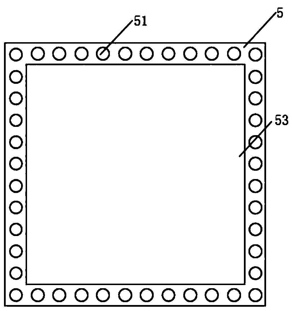
[0034] refer to figure 1 , 2 , the difference between the jet flow electrochemical deposition equipment of this embodiment and embodiment 1 is that: the diaphragm 3, the jet flow plate 4, and the fastening pad 5 are all in a circular shape, and the fastening pad 5 is provided with a number of second passages in an upper arc. A fastening nut 6 runs through the inner wall of the hole 52 and the second through hole 52 , and a circular groove 54 is opened on the fastening pad 5 .

[0035] Turn on the DC power supply 11, and at the same time, the circulation pump 17 discharges the catholyte in the storage tank 16 to the jet mechanism 2 through the catholyte inlet hole 8, and the jet plate 4 on the jet mechanism 2 sprays the catholyte into the cathode chamber 19 , and the substrate 12 on the substrate holder 13 in the cathode chamber 19 is electrolyzed, and the catholyte overflowed during the electrolysis is discharged into the storage tank 16 through the overflow hole 10 and the w...


PUM


Abstract

The invention discloses a jet flow type electrochemical deposition device. The device comprises an electroplating bath, wherein one or more jet flow mechanisms, cathodes and the anodes can be arrangedside by side in the electroplating tank, electrolysis on one or more substrates can be met, a substrate fixing frame is mounted in the electroplating tank, a substrate is mounted on the substrate fixing frame, the jet flow mechanisms are symmetrically arranged on the two sides of the substrate fixing frame, the jet flow mechanisms are provided with hollow shells, diaphragms and jet flow plates are mounted on the two sides of the jet flow mechanism respectively, cathode chambers are arranged on the side of the jet flow plates, and anode chambers are arranged on the side of the diaphragms. According to the device, through the design of the jet flow fixing plates, the diaphragms separate the catholyte in the cathode chamber and the anolyte in the anode chamber, an additive is not required tobe added in the solution in the anode chamber in the electrolysis process, the circular-shaped and the square-shaped jet flow plates are arranged, and the electrolysis of the plated objects in different shapes can be met, so that the electroplating effect of different plated objects is ensured.

Description

technical field [0001] The invention relates to the technical field of semiconductors, in particular to a jet-flow electrochemical deposition device. Background technique [0002] At present, the electroplating equipment used in industrial electroplating needs to reduce the thickness of the cathode film in order to increase the current density. Different methods are used to promote the flow of the solution to reduce the thickness of the cathode film. Some use mechanical stirring, some use air stirring, and some use cathode movement. Of course, there is also the method of using jet flow, and the plating speed can be improved to varying degrees. But each has its own disadvantages. The main disadvantages of the mechanical method are that the particles generated by the mechanical movement friction affect the quality of the electroplating, and the machinery itself is prone to failure, etc. The Eductor jet itself will shield the power line. The jet flow electroplating device has ...

Claims


Application Information

Patent Timeline
IPC IPC(8): C25D5/08C25D17/00C25D17/10
CPCC25D5/08C25D17/00C25D17/002C25D17/10
Inventor 侯利然熊邦国
Owner ANHUI HONGSHI AUTOMATION EQUIP CO LTD
Why Eureka
Try Eureka