A kind of current transformer production process and its production equipment

A technology for current transformers and production equipment, which is applied in the manufacture of inductors/transformers/magnets, circuits, electrical components, etc., can solve the problems of limited stirring range, poor stirring effect, and too fast stirring speed of the stirring paddle, so as to improve the stirring speed. Mixing effect, improving potting effect, smooth potting process

Active Publication Date: 2021-09-07
无锡德盛互感器有限公司
View PDF13 Cites 0 Cited by
  • Summary
  • Abstract
  • Description
  • Claims
  • Application Information

AI Technical Summary

Problems solved by technology

[0005] However, the epoxy mixed material in actual operation is stirred by an ordinary mixer. The ordinary mixer includes a stirring box and a stirring paddle connected to the stirring box. Because the stirring range of the stirring paddle is limited, the stirring effect of the ordinary mixer is relatively poor.
In this case, it is usually only possible to improve the stirring effect by prolonging the stirring time or increasing the rotation speed of the stirring paddle, but due to the particularity of the epoxy mixed material, it is generally required that the stirring time should not exceed one minute, and the stirring speed should not be too fast, so the actual The mixing effect of the epoxy mixture in the production is poor
Moreover, manual pouring is generally used during pouring. This pouring method is difficult to ensure the stability of pouring, resulting in poor filling and molding effects of epoxy hybrid materials.
In summary, the manufacturing quality of current transformers in the prior art needs to be improved

Method used


Image

  • A kind of current transformer production process and its production equipment
  • A kind of current transformer production process and its production equipment
  • A kind of current transformer production process and its production equipment

Examples


Embodiment 1

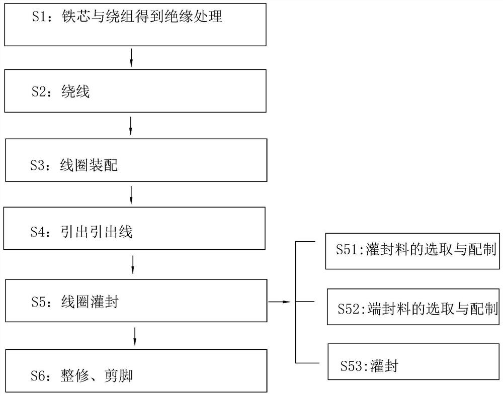
[0045] A kind of current transformer production process, with reference to figure 1 , including the following steps: S1: Insulation treatment of the iron core and the winding: wrapping the iron core with an insulating plastic shell, and wrapping the surface of the primary winding and the secondary winding with insulating tape;

[0046] S2: Winding: Winding the iron core. After the insulation of the iron core is completed, the primary winding is performed. After the primary winding is completed, the primary winding is wound with 0.08mm yellow wax silk. After the winding is completed, the secondary winding is performed to form a semi-finished current transformer. ;

[0047] S3: Coil assembly: Put the semi-finished transformer into the corresponding installation shell, and heat it with the tip of the electric soldering iron, so that the semi-finished transformer is fixedly connected to the installation shell.

[0048] S4: Lead-out lead-out line: lead the winding wire directly th...

Embodiment 2

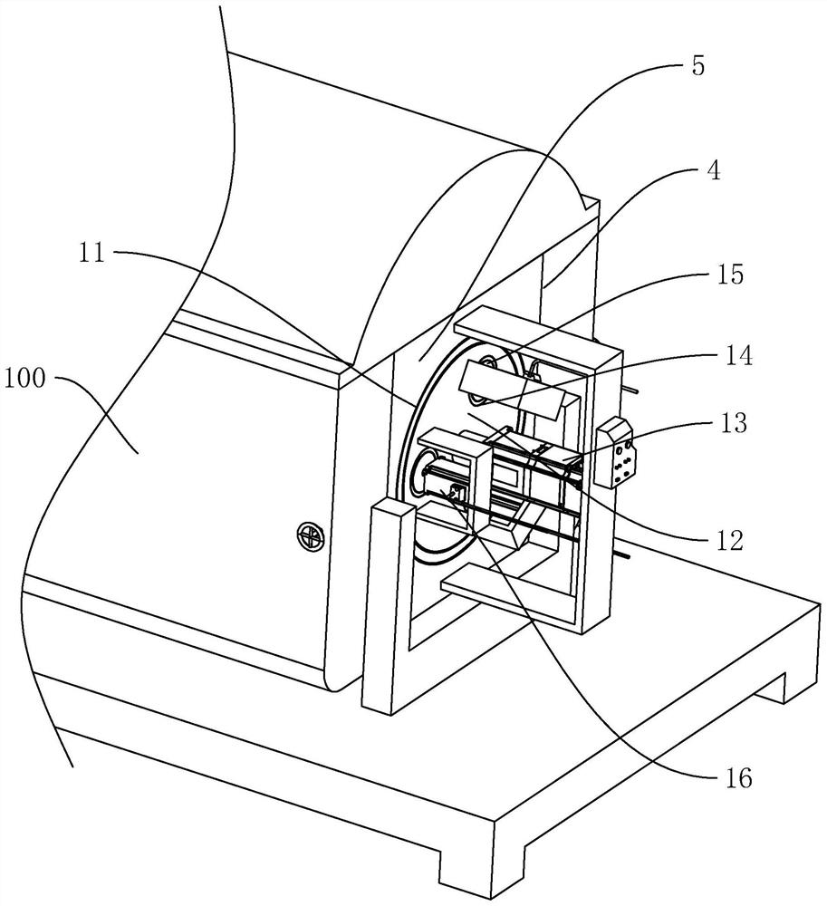
[0054] A kind of production equipment applied to the production process of current transformer in embodiment 1, with reference to image 3 and Figure 4 , The high-efficiency stirring tank 1 includes a tank body 100 and three stirring paddles 101 arranged in the tank body 100 .

[0055] Wherein, the tank body 100 is arranged as a cuboid, and a side wall of the tank body 100 is provided with an installation groove 4 , the inner cavity of the installation groove 4 is arranged in a cuboid shape and its notch is connected with the upper surface of the side wall of the tank body 100 .

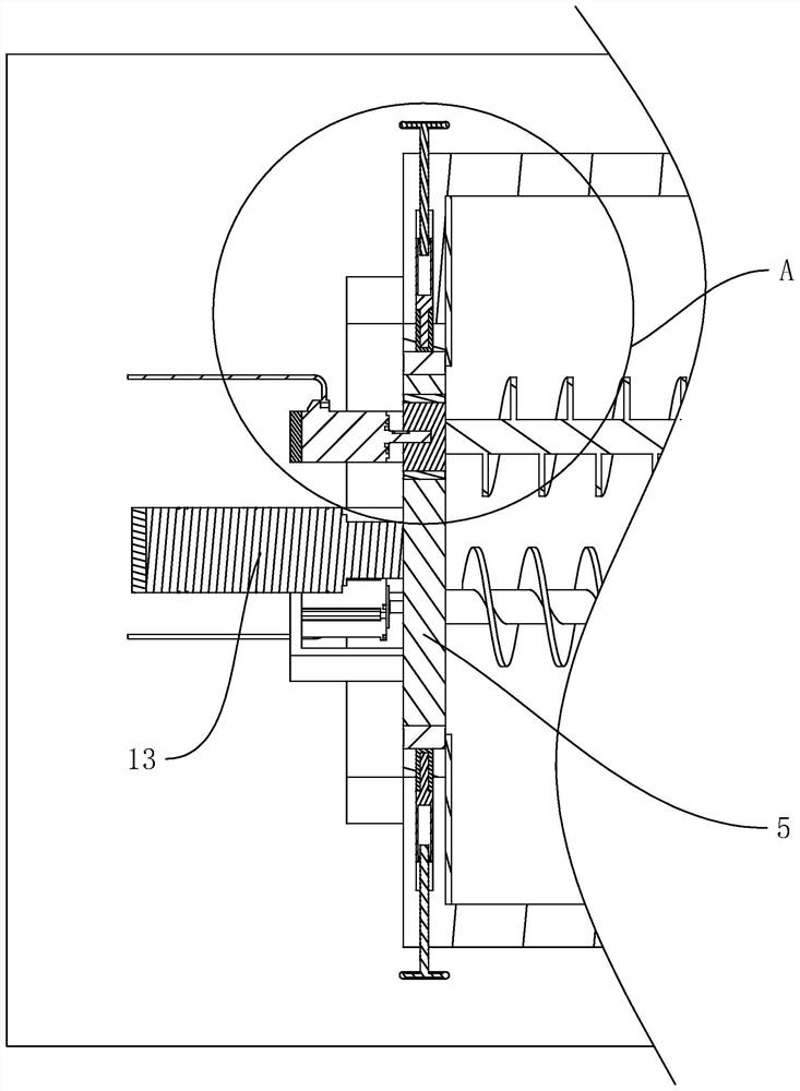
[0056] refer to figure 2 A mounting plate 5 is detachably connected to the mounting groove 4, and the mounting plate 5 is arranged in a cuboid shape and can slide to cover the notch of the mounting groove 4.

[0057] refer to image 3 and Figure 4 , between the mounting plate 5 and the mounting groove 4 is provided with a fixing device 6 for fixing the mounting plate 5, the fixing device 6 inc...

Embodiment 3

[0074] Embodiment 3: a kind of production equipment applied to the production process of current transformer in embodiment 1, refer to Figure 6 The difference from Embodiment 2 is that the fixing device 6 includes a positioning rod 64 fixedly connected to the mounting plate 5 and a positioning groove 65 opened on the wall of the mounting groove 4 for inserting the positioning rod 64 . in. The positioning rod 64 is arranged in a cylindrical shape and arranged along a direction parallel to the surface of the mounting plate 5 .

[0075]When the mounting plate 5 is inserted into the mounting groove 4 , the positioning rod 64 is inserted into the positioning groove 65 , and the position of the mounting plate 5 is fixed when the positioning rod 64 is inserted into the positioning groove 65 .


PUM

PropertyMeasurementUnit
lengthaaaaaaaaaa

Abstract

The invention discloses a production process of a current transformer, which belongs to the technical field of transformer production. The key points of the technical scheme are S5: coil potting; S51: selection and preparation of potting material; S52: selection and preparation of end sealing material ; S53: Potting: The shell mouth of the installation shell is set vertically upwards, and the end seal material is first applied to the side wall of the installation shell facing away from the shell opening of the installation shell through the seal material filling device, and the potting material is poured out after the seal material is cured. Pour into the installation shell, first fill the potting material to half the height of the installation shell, and then fill the installation shell until it is flush with the opening of the plastic shell after the potting compound is cured, which has the advantage of improving the quality of the current transformer It also discloses a production process and production equipment for the above-mentioned current transformer, which can improve the stirring and mixing effect of the insulating epoxy potting material and the epoxy sealing adhesive, and improve the potting effect of the potting material on the installation shell .

Description

technical field [0001] The invention relates to the technical field of transformer production, in particular to a production process of a current transformer and production equipment thereof. Background technique [0002] Transformer, also known as instrument transformer, is a general term for current transformer and voltage transformer. It can change high voltage into low voltage and high current into small current for measurement or protection system. Its function is mainly to convert high voltage or high current into standard low voltage (100V) or standard small current (5A or 1A, both refer to rated value) in proportion, so as to realize the standardization and miniaturization of measuring instruments, protection equipment and automatic control equipment. change. At the same time, the transformer can also be used to isolate the high-voltage system to ensure the safety of people and equipment. [0003] The production process of the existing current transformer is as fo...

Claims


Application Information

Patent Timeline
Patent Type & Authority Patents(China)
IPC IPC(8): H01F41/00H01F41/06H01F41/12
CPCH01F41/005H01F41/06H01F41/12
Inventor 虞迅遂邹微竹吴伟平
Owner 无锡德盛互感器有限公司
Why Eureka
Try Eureka