Organic electroluminescent device, display panel and display device

An electroluminescence device and electroluminescence technology, which are applied in electric solid devices, luminescent materials, electrical components, etc., can solve the problems of small display color gamut area and low color purity of devices, and achieve narrow emission spectrum and large display color gamut. Small area and Stokes displacement

Active Publication Date: 2020-04-17
KUNSHAN GO VISIONOX OPTO ELECTRONICS CO LTD
View PDF3 Cites 23 Cited by
  • Summary
  • Abstract
  • Description
  • Claims
  • Application Information

AI Technical Summary

Problems solved by technology

[0003] At present, the dyes of green organic electroluminescent devices are mostly phosphorescent materials, and their half-peak widths are relatively wide, generally greater than 50nm, which makes the color purity of phosphorescent materials low, resulting in a small display color gamut area of ​​the screen.

Method used


Image

  • Organic electroluminescent device, display panel and display device
  • Organic electroluminescent device, display panel and display device
  • Organic electroluminescent device, display panel and display device

Examples


Synthetic example 1

[0096] Synthesis Example 1: Synthesis of Compound C-1

[0097]

[0098] Under a nitrogen atmosphere, a pentane solution of tert-butyllithium (11.09mL, 1.60M, 17.74mmol) was slowly added to a solution of C-1-1 (8.00g, 14.79mmol) in tert-butylbenzene (150mL) at 0°C Then, the temperature was raised to 80°C, 100°C, and 120°C for 1 hour each. After the reaction, the temperature was lowered to -30°C, boron tribromide (5.56g, 22.18mmol) was slowly added, and stirring was continued for 0.5 hour at room temperature. N,N-diisopropylethylamine (3.82g, 29.57mmol) was added at room temperature, and the reaction was continued at 145°C for 5 hours and then stopped. The solvent was spin-dried in vacuo and passed through a silica gel column (developing solvent: ethyl acetate: petroleum ether = 50:1) to obtain target compound C-1 (1.00 g, 13% yield, HPLC analytical purity 99.56%) as a yellow solid. MALDI-TOF-MS results: molecular ion peak: 514.45; elemental analysis results: theoretical value: C...

Synthetic example 2

[0099] Synthesis Example 2: Synthesis of Compound C-2

[0100]

[0101] The difference between this example and Synthesis Example 1 is that in this example, C-1-1 needs to be replaced with C-2-1 in the same amount. The target compound C-2 (1.00 g, 13% yield, HPLC analytical purity 99.66%) was a yellow solid. MALDI-TOF-MS results: molecular ion peak: 512.45 Elemental analysis results: theoretical value: C, 84.39%; H, 4.33%; B, 2.11%; F, 3.71%; N, 5.47%; experimental value: C, 84.42 %; H, 4.01B, 2.52; F, 3.51%; N, 5.54%.

Synthetic example 3

[0102] Synthesis Example 3: Synthesis of Compound C-6

[0103]

[0104] The difference between this example and Synthesis Example 1 is that in this example, C-1-1 needs to be replaced with C-6-1 in the same amount. The target compound C-6 (0.62 g, 8% yield, HPLC analytical purity 99.56%), was a yellow solid. MALDI-TOF-MS results: molecular ion peak: 542.32 elemental analysis results: theoretical value: C, 79.72%; H, 3.72%; B, 1.99%; F, 3.50%; N, 5.17%; O, 5.90%; experiment Values: C, 79.77%; H, 3.72%; B, 1.94%; F, 3.55%; N, 5.17%; O, 5.85%.


PUM

PropertyMeasurementUnit
thicknessaaaaaaaaaa
thicknessaaaaaaaaaa
thicknessaaaaaaaaaa

Abstract

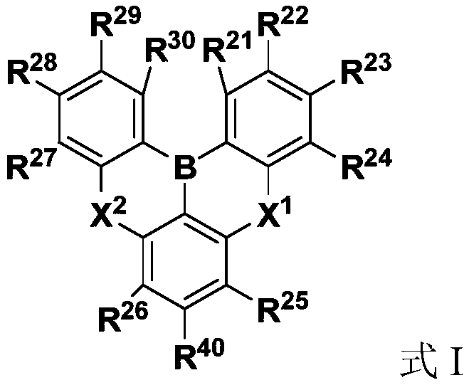
The invention relates to an organic electroluminescent device, a display panel and a display device. The organic electroluminescent device comprises a first electrode, a second electrode and an organic layer located between the first electrode and the second electrode. The organic layer comprises a light-emitting layer, the light-emitting layer contains a main material, a thermal activation delayed fluorescence sensitizer and a green fluorescent dye, and the green fluorescent dye has a structure as shown in a formula I. The thermal activation sensitization fluorescence technology is used, andthe green fluorescent dye with a specific structure, the sensitizing agent and the main material are matched for use so that the effects of narrowing the spectrum of the device and improving the colorpurity of green light are achieved, the device has the efficiency equivalent to that of a phosphorescent green light device, and the display panel comprising the device has a relatively high displaycolor gamut area.

Description

Technical field [0001] The present invention relates to the field of organic electroluminescence technology, in particular to an organic electroluminescence device, a display panel and a display device. Background technique [0002] In the Thermally Activated Sensitized Fluorescence (TASF, Thermally Activated Sensitized Fluorescence) system, when a thermally activated delayed fluorescence (TADF) material is used as a sensitizer, the energy of the host material is transferred to the TADF material, and then its triplet energy passes through the reverse system. The RISC process returns to the singlet state, and then transfers energy to the doped fluorescent dye to emit light. This can achieve complete energy transfer from the host to the dye molecule, so that the traditional fluorescent doped dye can also exceed the internal quantum efficiency of 25% limit. [0003] At present, most of the dyes of green organic electroluminescence devices are phosphorescent materials, and their half-...

Claims


Application Information

Patent Timeline
Patent Type & Authority Applications(China)
IPC IPC(8): H01L51/50H01L27/32
CPCH10K59/00H10K50/121H10K50/125C09K11/06C09K2211/1055H10K85/654H10K85/322H10K85/791H10K85/6572H10K50/11H10K2101/20H10K85/324H10K85/622H10K85/624H10K85/626H10K85/633H10K85/636H10K85/6574H10K85/6576H10K50/15H10K50/17H10K2101/10
Inventor 李国孟张跃威周小康姚纯亮秦齐齐
Owner KUNSHAN GO VISIONOX OPTO ELECTRONICS CO LTD
Why Eureka
Try Eureka