
Micro-rough electrolytic copper foil and copper foil substrate

A technology of electrolytic copper foil and copper foil substrate, applied in the direction of printed circuits, printed circuits, electrical components, etc., can solve the problems of falling peel strength between copper foil and substrate, reducing roughness, affecting the yield of back-end products, etc. Achieve good bonding force, suppress loss, and good insertion loss

Active Publication Date: 2020-04-17
CO TECH DEV CORP
View PDF5 Cites 2 Cited by
  • Summary
  • Abstract
  • Description
  • Claims
  • Application Information

AI Technical Summary

Problems solved by technology

However, while reducing the roughness, it will also lead to a decline in the peel strength between the copper foil and the substrate, which will affect the yield of the back-end products

Method used


Image

  • Micro-rough electrolytic copper foil and copper foil substrate
  • Micro-rough electrolytic copper foil and copper foil substrate
  • Micro-rough electrolytic copper foil and copper foil substrate

Examples


Embodiment 1

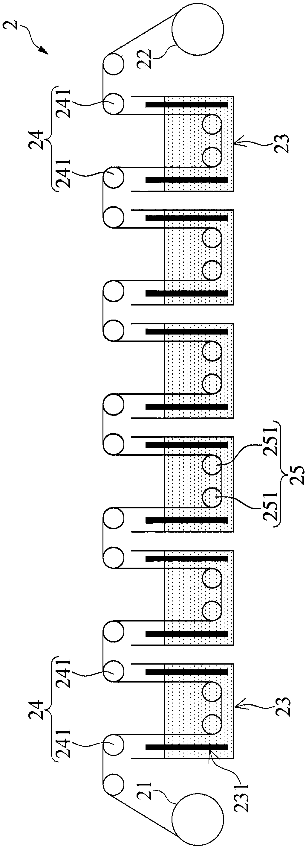
[0045] refer to image 3 , Micro-rough electrolytic copper foil is roughened by continuous electrolytic equipment 2. The continuous electrolysis equipment 2 comprises a feeding roller 21, a collecting roller 22, six grooves 23 between the feeding roller 21 and the collecting roller 22, six electrolytic roller groups 24 placed respectively above the groove 23, And six auxiliary roller groups 25 respectively located in the grooves 23. A set of platinum electrodes 231 is disposed in each groove 23 . Each electrolytic roller group 24 includes two electrolytic rollers 241. Each auxiliary roller set 25 includes two auxiliary rollers 251 . The platinum electrode 231 in each tank 23 and the corresponding electrolytic roller set 24 are respectively electrically connected to the anode and the cathode of the external power supply.

[0046] In this embodiment 1, reversed copper foil (RTF) was used as the raw foil, which was purchased from Jinju Development Co., Ltd. (model RG311). Th...

Embodiment 2 and 3

[0052] The components of raw foil, electrolytic equipment and copper-containing plating solution are the same as in Example 1, the electroplating conditions are shown in Table 1, and the production speed is 10 m / min. Then, take two pieces of micro-rough electrolytic copper foil and one piece of base material IT170GRA1 and stick them together to complete the production. The measurement method is the same as in Example 1, and the test results are listed in Table 2.


PUM

PropertyMeasurementUnit
Roughnessaaaaaaaaaa
Widthaaaaaaaaaa
Particle sizeaaaaaaaaaa

Abstract

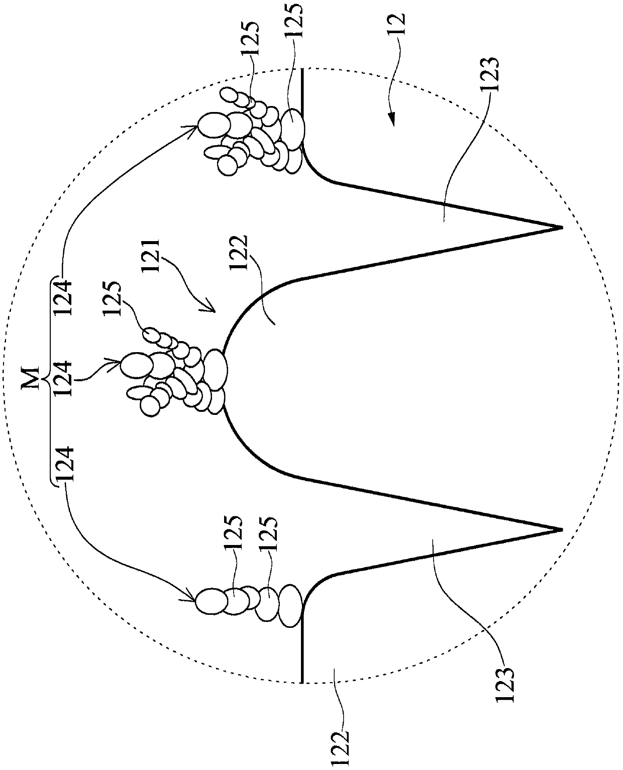
The invention discloses a micro-rough electrolytic copper foil and a copper foil substrate. The micro-rough electrolytic copper foil comprises a micro-rough surface. The micro-rough surface is provided with a plurality of convex edges, a plurality of grooves and a plurality of micro-crystal clusters. The groove has a U-shaped section profile and / or a V-shaped section profile, the average width ofthe grooves ranges from 0.1 micrometer to 4 micrometers, and the average depth of the grooves is smaller than or equal to 1.5 micrometers. The micro-crystal clusters are positioned at the tops of theconvex edges. Each micro-crystal cluster is composed of a plurality of micro-crystal stacks with the average diameter smaller than or equal to 0.5 micrometer. The Rlr value of the micro-rough surfaceof the micro-rough electrolytic copper foil is lower than 1.3. Good bonding force exists between the micro-rough surface and the base material, good intervention loss is shown, and signal loss can beeffectively restrained.

Description

technical field [0001] The invention relates to a copper foil, in particular to an electrolytic copper foil and a copper foil substrate with the copper foil. Background technique [0002] With the development of information and electronics industry, high-frequency and high-speed signal transmission has become a part of modern circuit design and manufacture. In order to meet the high-frequency and high-speed signal transmission requirements of electronic products, the copper foil substrates used must have good insertion loss performance at high frequencies to prevent excessive loss of high-frequency signals during transmission. The insertion loss of copper clad substrate is highly related to its surface roughness. When the surface roughness is reduced, the insertion loss has a better performance, and vice versa. However, while reducing the roughness, it will also lead to a decrease in the peel strength between the copper foil and the substrate, which will affect the yield o...

Claims


Application Information

Patent Timeline
IPC IPC(8): H05K1/09C25F3/02
CPCH05K1/09C25F3/02H05K2201/0373H05K2201/0355
Inventor 宋云兴高羣祐吴宗宪
Owner CO TECH DEV CORP
Learn More