Voltage converter and voltage change control method

A technology of a voltage converter and a control method, which is applied to conversion equipment without intermediate conversion to AC, conversion of DC power input to DC power output, electrical components, etc., which can solve the problem of increased electromagnetic noise and increased loss of main switches and magnetic components , conversion efficiency decline and other issues

Inactive Publication Date: 2020-04-21
ANHUI POLYTECHNIC UNIV MECHANICAL & ELECTRICAL COLLEGE
View PDF0 Cites 4 Cited by
  • Summary
  • Abstract
  • Description
  • Claims
  • Application Information

AI Technical Summary

Problems solved by technology

[0003] The miniaturization and miniaturization of magnetic components (inductors or transformers) is one of the key technologies for the integration of power electronic systems. It is undoubtedly a very effective measure to increase the switching frequency under the soft switching technology, so that the volume of the inductor and transformer in the circuit is reduced. It can be reduced, and the performance of the entire circuit is improved; however, when the switching frequency reaches about 400kHz-500kHz, the loss of the main switch and magnetic components increases, the conversion efficiency decreases, the electromagnetic noise increases, and the volume of the filter capacitor used to suppress noise also decreases. With the increase, increasing the switching frequency can only bring negative impacts, so there is no room for reducing the power supply volume by increasing the switching frequency

Method used


Image

  • Voltage converter and voltage change control method
  • Voltage converter and voltage change control method

Examples


Embodiment Construction

[0017] Specific embodiments of the present invention will be described in detail below in conjunction with the accompanying drawings. It should be understood that the specific embodiments described here are only used to illustrate and explain the present invention, and are not intended to limit the present invention.

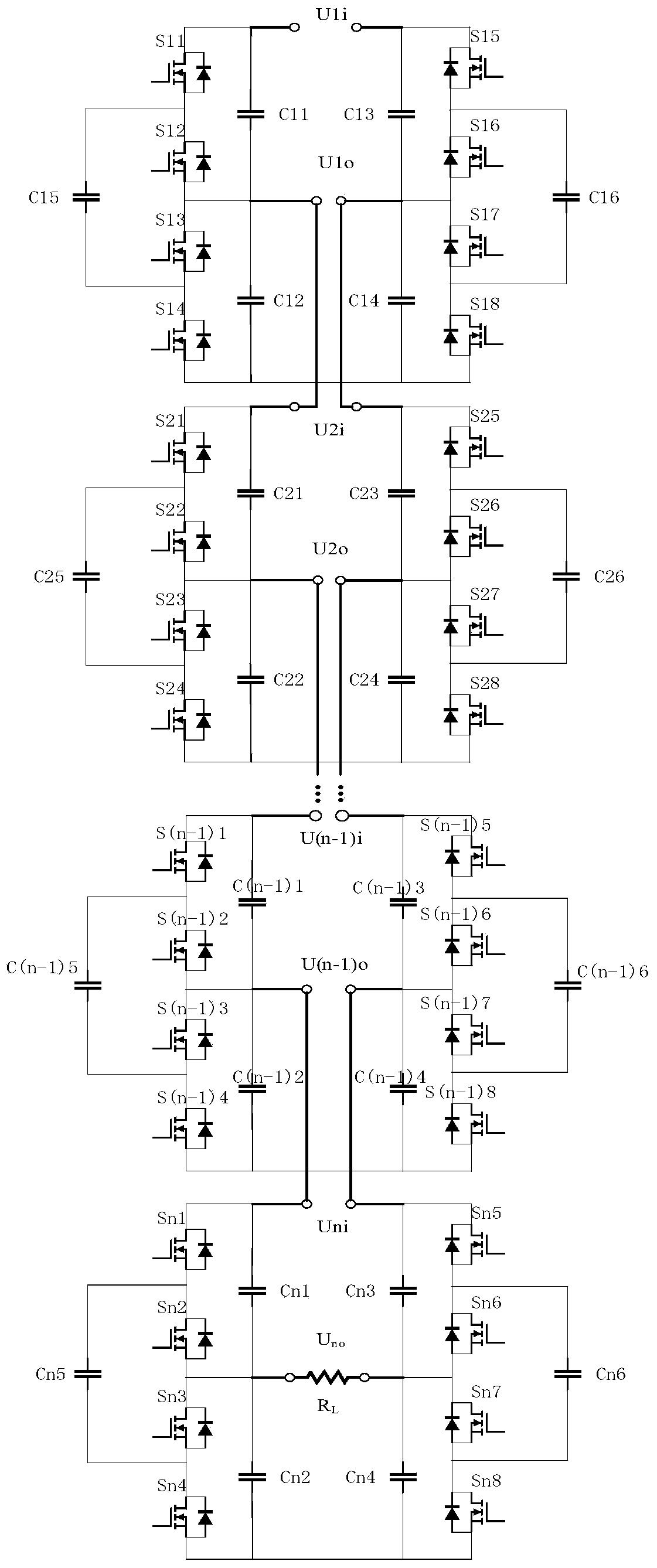
[0018] figure 1 A voltage converter according to this embodiment, the voltage converter includes: a plurality of sequentially cascaded basic unit circuits including two bridge arms symmetrically arranged and having the same circuit structure, wherein any one of the bridge arms includes: The following four power switch tubes are sequentially connected in series in the first position power switch tube, the second position power switch tube, the third position power switch tube and the fourth position power switch tube, and the second position power switch tube and the first position power switch tube The three-position power switch tube is configured as a cascadi...


PUM


Abstract

The embodiment of the invention discloses a voltage converter and a voltage change control method. The voltage converter comprises a plurality of basic unit circuits and a control signal transmissioncircuit, wherein the plurality of basic unit circuits are sequentially cascaded, and each basic unit circuit comprises two bridge arms which are symmetrically arranged and have the same circuit structure. Any one bridge arm comprises the following components: four power switch tubes which are sequentially connected in series; a first position capacitor connected in parallel with the first positionpower switch tube and the second position power switch tube; a second position capacitor connected in parallel with the third position power switch tube and the fourth position power switch tube; anda fifth position capacitor connected in parallel with the second position power switch tube and the third position power switch tube. The control signal transmission circuit is used for generating and sending control signals to control eight power switch tubes in two bridge arms in each of the cascaded basic unit circuits to be switched on by stages, so that the basic unit circuit outputs an input voltage after reducing the input voltage, and the voltage outputted by the basic unit circuit is configured to be obtained based on the number of the basic unit circuits. With the voltage converterand the voltage change control method of the invention adopted, non-inductive voltage change is realized.

Description

technical field [0001] The invention relates to the field of non-inductive components, in particular to a voltage converter and a voltage change control method. Background technique [0002] Traditional power conversion usually uses electromagnetic transformers, which have the advantages of electrical isolation, high efficiency, and large capacity, but also have disadvantages such as large volume, large audio noise, and harmonic pollution. With the development of miniaturization of electronic equipment, traditional electromagnetic transformers cannot meet the requirements of miniaturization of electronic equipment. [0003] The miniaturization and miniaturization of magnetic components (inductors or transformers) is one of the key technologies for the integration of power electronic systems. It is undoubtedly a very effective measure to increase the switching frequency under the soft switching technology, so that the volume of the inductor and transformer in the circuit is r...

Claims


Application Information

Patent Timeline
IPC IPC(8): H02M3/07
CPCH02M3/07H02M3/072
Inventor 李娟
Owner ANHUI POLYTECHNIC UNIV MECHANICAL & ELECTRICAL COLLEGE
Why Eureka
Try Eureka