
Power balance controller, virtual impedance-based bipolar MMC converter station passive control strategy and flexible direct-current power transmission system

A power balance and controller technology, which is applied in the direction of converting AC power input to DC power output, output power conversion devices, electrical components, etc. Effects avoided by synchronizing AC power

Active Publication Date: 2020-04-21
POWERCHINA HUADONG ENG COPORATION LTD
View PDF6 Cites 3 Cited by
  • Summary
  • Abstract
  • Description
  • Claims
  • Application Information

AI Technical Summary

Problems solved by technology

[0005] However, with the gradual increase in the scale of new energy electric fields in the future, the power required to be transmitted by the grid-connected system will also increase rapidly. At this time, the MMC power transmission system with a symmetrical unipolar structure can no longer meet the needs of power transmission. MMC with bipolar structure to send offshore wind power
However, when using a bipolar structure, if both the positive and negative inverters adopt the control mode of constant voltage frequency and voltage amplitude, the output voltages of the two inverters will affect each other and cause oscillation, which is not conducive to system stability.

Method used


Image

  • Power balance controller, virtual impedance-based bipolar MMC converter station passive control strategy and flexible direct-current power transmission system
  • Power balance controller, virtual impedance-based bipolar MMC converter station passive control strategy and flexible direct-current power transmission system
  • Power balance controller, virtual impedance-based bipolar MMC converter station passive control strategy and flexible direct-current power transmission system

Examples


Embodiment Construction

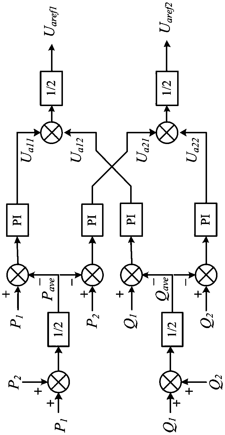
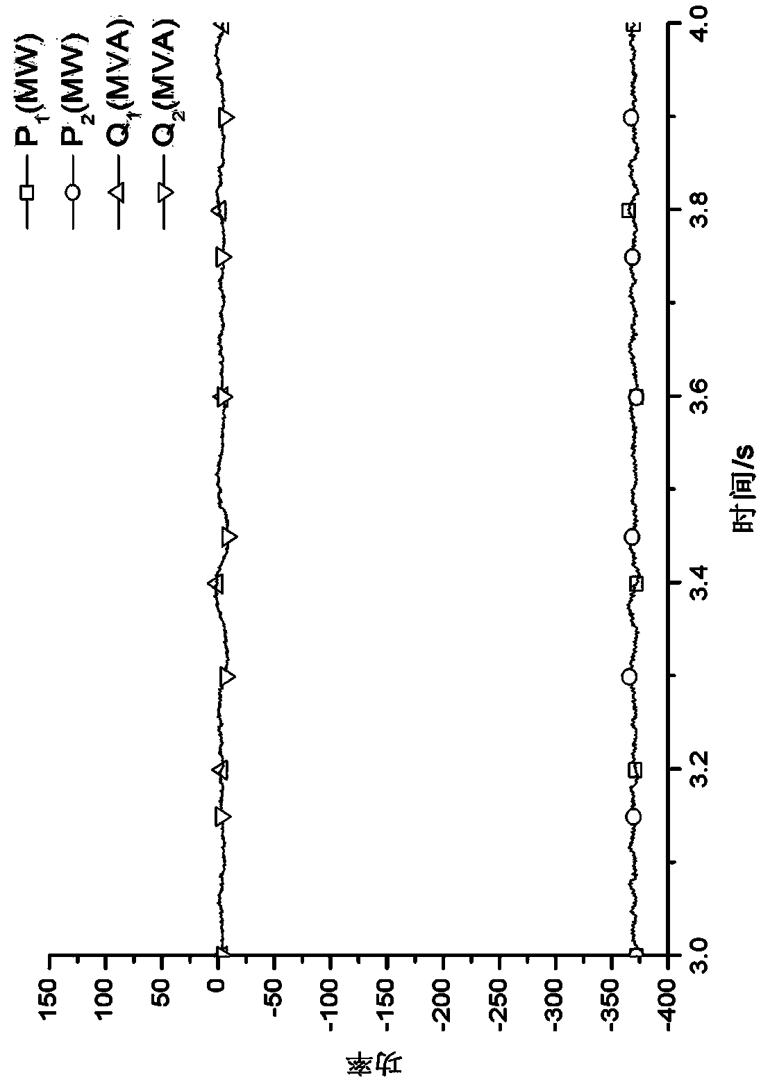
[0029] Such as figure 1 As shown, this embodiment provides a flexible DC transmission system, which is a two-terminal bipolar system with a rated DC voltage of ±400kV and a rated transmission power of 800MW. One of the converter stations is connected to the power grid, and the other converter station is connected to the power grid. It is connected by a passive system, which includes a new energy electric field with a total rated capacity of 800MVA, and the active power generated during the test is 750MW. Each pole is connected to the AC system through an MMC converter with a rated voltage of 400kV. The specific parameters of a single converter are shown in Table 1.

[0030]

[0031] Table 1

[0032] In this example, the transmission system adopts the passive control strategy of the bipolar MMC converter station based on virtual impedance to control the positive and negative MMC converters. The specific control steps are as follows:

[0033] 1. In the passive control strat...


PUM


Abstract

The invention relates to a power balance controller, a virtual impedance-based bipolar MMC converter station passive control strategy and a flexible direct-current power transmission system. With thepower balance controller, the virtual impedance-based bipolar MMC converter station passive control strategy and the flexible direct-current power transmission system adopted, the mutual influence ofthe output voltages of two converters can be avoided. According to the technical schemes of the invention, the power balance controller is characterized in that the power balance controller is used for balancing the active power and reactive power exchanged between the positive and negative MMC converters and an alternating-current system and providing alternating-current voltage amplitude instruction values for the positive and negative MMC converters. The operation process of the power balance controller comprises the following steps of: acquiring active power P1 and reactive power Q1 inputted to the alternating-current system by the positive MMC converter, and active power P2 and reactive power Q2 inputted to the alternating-current system by the negative MMC converter; and calculatingthe active power average value Pave and reactive power average value Qave of the positive and negative MMC converters. The power balance controller of the invention is applicable to the technical field of power system power transmission and distribution.

Description

technical field [0001] The invention relates to a power balance controller, a passive control strategy of a bipolar MMC converter station based on virtual impedance and a flexible direct current transmission system, which is applicable to the technical field of power transmission and distribution in electric power systems. Background technique [0002] In recent years, in order to reduce the consumption of fossil resources and prevent and control ecological environment pollution, my country has vigorously supported the development of new energy power generation industries, such as photovoltaic power generation and wind power generation. However, the new energy electric field has the characteristics of weak fault ride-through capability and strong volatility, so it needs to be connected to the grid through specific technical means. [0003] The voltage source converter based high voltage direct current (VSC-HVDC) technology has the advantages of flexible control, does not req...

Claims


Application Information

Patent Timeline
IPC IPC(8): H02M7/00H02M7/493H02J3/36
CPCH02J3/36H02M7/00H02M7/493Y02E60/60
Inventor 傅春翔陈晴杨林刚汪天呈薛源徐鸥洋高玉青杨文斌周才全徐志辉郦洪柯
Owner POWERCHINA HUADONG ENG COPORATION LTD
Learn More