A receiving transducer with adjustable working frequency

A technology of working frequency and transducers, applied in piezoelectric/electrostrictive transducers, instruments, sensors, etc., can solve the problems of low sensitivity receiving response, narrow frequency band application range, low sensitivity, etc., and achieve flat receiving response , The overall structure and manufacturing process are simple, and the effect of improving sensitivity

Active Publication Date: 2021-10-12
SHAANXI NORMAL UNIV
View PDF0 Cites 0 Cited by
  • Summary
  • Abstract
  • Description
  • Claims
  • Application Information

AI Technical Summary

Problems solved by technology

However, the sensitivity of the receiving transducer in the prior art is low and the frequency band of the receiving response is narrow. A receiving transducer structure can only meet the sound wave reception of a single frequency, and the sensitivity is not high, which has led to problems in real life. When it is used in the middle of the world, it is necessary to use a variety of receiving transducers to receive sound signals in various frequency bands, which are large in size and complex in structure, which brings a lot of inconvenience to practical applications.

Method used


Image

  • A receiving transducer with adjustable working frequency
  • A receiving transducer with adjustable working frequency
  • A receiving transducer with adjustable working frequency

Examples


Embodiment 1

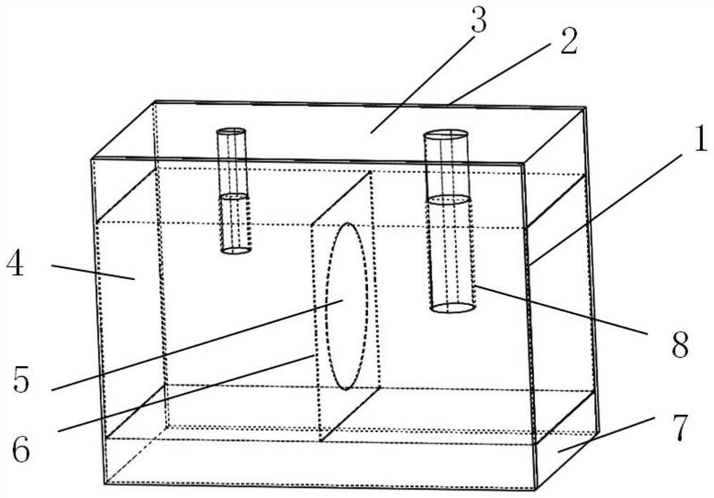
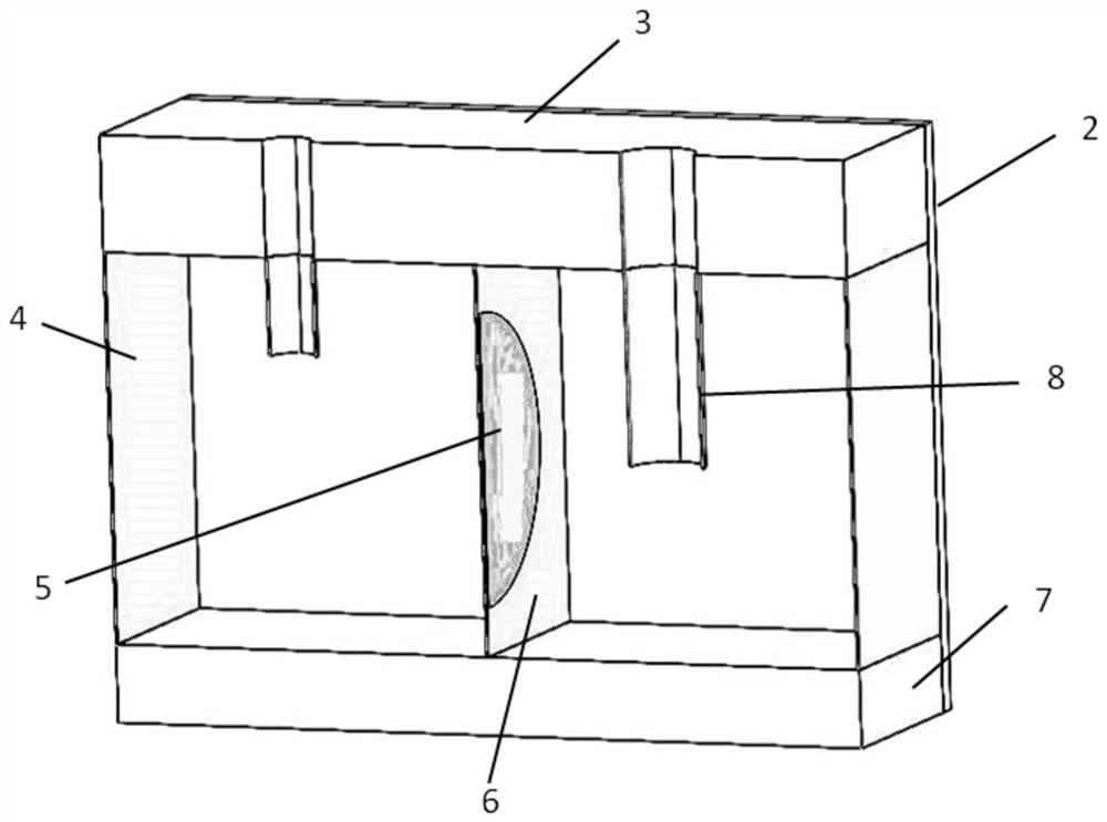
[0031] Embodiment 1, adjust the lengths of the thin-walled circular tube extension necks 8 of the two Helmholtz resonant cavities to be L respectively 1 =0mm,L 2 = 9 mm. Use finite element software to model and calculate the voltage value received by the terminal when a plane wave with a sound pressure amplitude of 1 Pa is incident vertically on the top wall 3 of the opening. Through calculation, the extension neck 8 of the thin-walled circular tube is L 1 =0mm,L 2 = The receiving sensitivity frequency response curve at 9mm, please refer to the attached Figure 4 , it can be clearly seen from the figure that the high-sensitivity reception above -30 decibels is achieved near 424Hz.

Embodiment 2

[0032] Embodiment 2, adjust the lengths of the thin-walled circular tube extension necks 8 of the two Helmholtz resonant cavities to be L respectively 1 =15mm, L 2 = 0 mm. Use finite element software to model and calculate the voltage value received by the terminal when a plane wave with a sound pressure amplitude of 1 Pa is incident vertically on the top wall 3 of the hole, and calculate the extension neck 8 of the thin-walled circular tube as L 1 =15mm,L 2 For the frequency response curve of receiving sensitivity at =0mm, please refer to the attached Figure 5 , it can be clearly seen from the figure that a flat sensitivity receiving response is achieved in a wide frequency band.

Embodiment 3

[0033] Embodiment 3, adjust the lengths of the thin-walled circular tube extension necks 8 of the two Helmholtz resonant cavities to be L respectively 1 =5mm,L 2 = 10 mm. Use finite element software to model and calculate the voltage value received by the terminal when a plane wave with a sound pressure amplitude of 1 Pa is incident vertically on the top wall 3 of the opening. Through calculation, the extension neck 8 of the thin-walled circular tube is L 1 =5mm,L 2 = 10mm receiving sensitivity frequency response curve, please refer to the attached Figure 6 , it can be clearly seen from the figure that the sensitivity reception above -40 decibels has been achieved at 300Hz-450Hz.

[0034] The invention realizes a receiving transducer with adjustable working frequency which has a high-sensitivity receiving response to a single-frequency acoustic signal and a flat receiving response to a wide-band acoustic signal. The opposite sound pressure phase will be generated in the c...


PUM


Abstract

The invention discloses a receiving transducer with adjustable working frequency, which comprises a plurality of coupled Helmholtz resonant cavity structural units arranged together, and the coupled Helmholtz resonant cavity structural unit includes a thin-walled circular tube extension neck, A piezoelectric material and two coupled Helmholtz resonant cavities, the Helmholtz resonant cavity includes a top wall with openings, a bottom wall without openings, side walls, and a front panel and a rear panel, the The side wall is located between the two coupled Helmholtz resonant cavity structural units, and the front panel and the rear panel are used to form a closed cavity; the openings of the top walls of the two Helmholtz resonant cavities have the same or different sizes, In addition, an extension neck of a thin-walled circular tube is interspersed in the opening of the top wall, and a piezoelectric material is arranged between the two Helmholtz resonant cavities, and the piezoelectric material is formed by pressing piezoelectric ceramic sheets and electrode sheets. The overall structure and manufacturing process of the present invention are simple, easy to be processed in an array to improve sensitivity, and can also be processed in series and parallel according to needs, and the cost is low.

Description

technical field [0001] The invention belongs to the field of transducers, in particular to a receiving transducer with adjustable working frequency. Background technique [0002] In the field of receiving transducers, operating frequency and sensitivity are two important performance indicators. The most common receiving transducer uses external sound waves to act on the vibrating surface of the transducer, thereby causing the mechanical vibration system of the transducer to occur. Vibration, with the help of certain physical effects, such as piezoelectric effect, magnetostrictive effect, etc., causes corresponding changes in the electric field or magnetic field in the energy storage element of the transducer, thereby causing the electrical output of the transducer to generate a voltage equivalent to the acoustic signal and current. Regarding the receiving transducer, many scholars have done relevant research. Di Pengfei, South China Sea Institute of Oceanology, Chinese Aca...

Claims


Application Information

Patent Timeline
Patent Type & Authority Patents(China)
IPC IPC(8): H04R17/00G01H11/08
CPCG01H11/08H04R17/00
Inventor 张小凤孙琳张光斌
Owner SHAANXI NORMAL UNIV
Why Eureka
Try Eureka