Mold and molding system

A technology for molds and molded products, which is applied in the field of molds and molding systems, and can solve problems such as difficult management of lubricant quantity, time-consuming, and insufficient release agent.

Active Publication Date: 2020-04-21
SHIPPO KANAGATA INDS
View PDF11 Cites 2 Cited by
  • Summary
  • Abstract
  • Description
  • Claims
  • Application Information

AI Technical Summary

Problems solved by technology

It takes time to cool the mold from this high temperature to the temperature at which the release agent can be sprayed in a mist form, and the efficiency of the molding operation cannot be improved.
On the other hand, there is a problem that if the release agent is sprayed excessively in mist form without waiting for the cooling of the mold, only the surface of the mold is rapidly cooled.
[0007] However, in the case of the technique described in Patent Document 1, there is a problem that the release agent needs to be contained in the entire region of the porous material constituting the inner mold. , requires a large amount of release agent
In addition, because each mold has a different shape, it is difficult to determine the arrangement position, number, and diameter of the supply path so that the release agent can be evenly exuded from the inner surface
Furthermore, there is a problem that the release agent tends to leak out of the mold from the gap between the outer mold and the inner mold caused by the temperature change of the mold accompanying casting, and it is also difficult to control the supply amount of the release agent.
[0012] However, according to this technique, there is a problem that if the release agent is supplied to the medium-density region through the low-density region, the release agent needs to permeate the entire low-density region. On the molding surface of the mold, the release agent flows out from the low-density area, and the amount of release agent used increases, and the release agent that penetrates into the upper mold molding surface tends to become insufficient, and it is difficult to manage, so that the low-density area Hold release agent evenly
[0017] However, according to the technique described in Patent Document 5, there is a problem that if the molding surface of the mold is arranged vertically in the same way as the normal arrangement of the mold, the release agent is likely to be released from the low-density region as in the technique described in Patent Document 3. Since it flows out, it is not easy to manage the amount of lubricant, etc. inside the mold. If there is insufficient lubricant, etc., it can only be supplied by mist spraying from the inner surface of the mold, and the supply of lubricant, etc., is time-consuming and laborious.

Method used


Image

  • Mold and molding system
  • Mold and molding system
  • Mold and molding system

Examples


no. 1 example

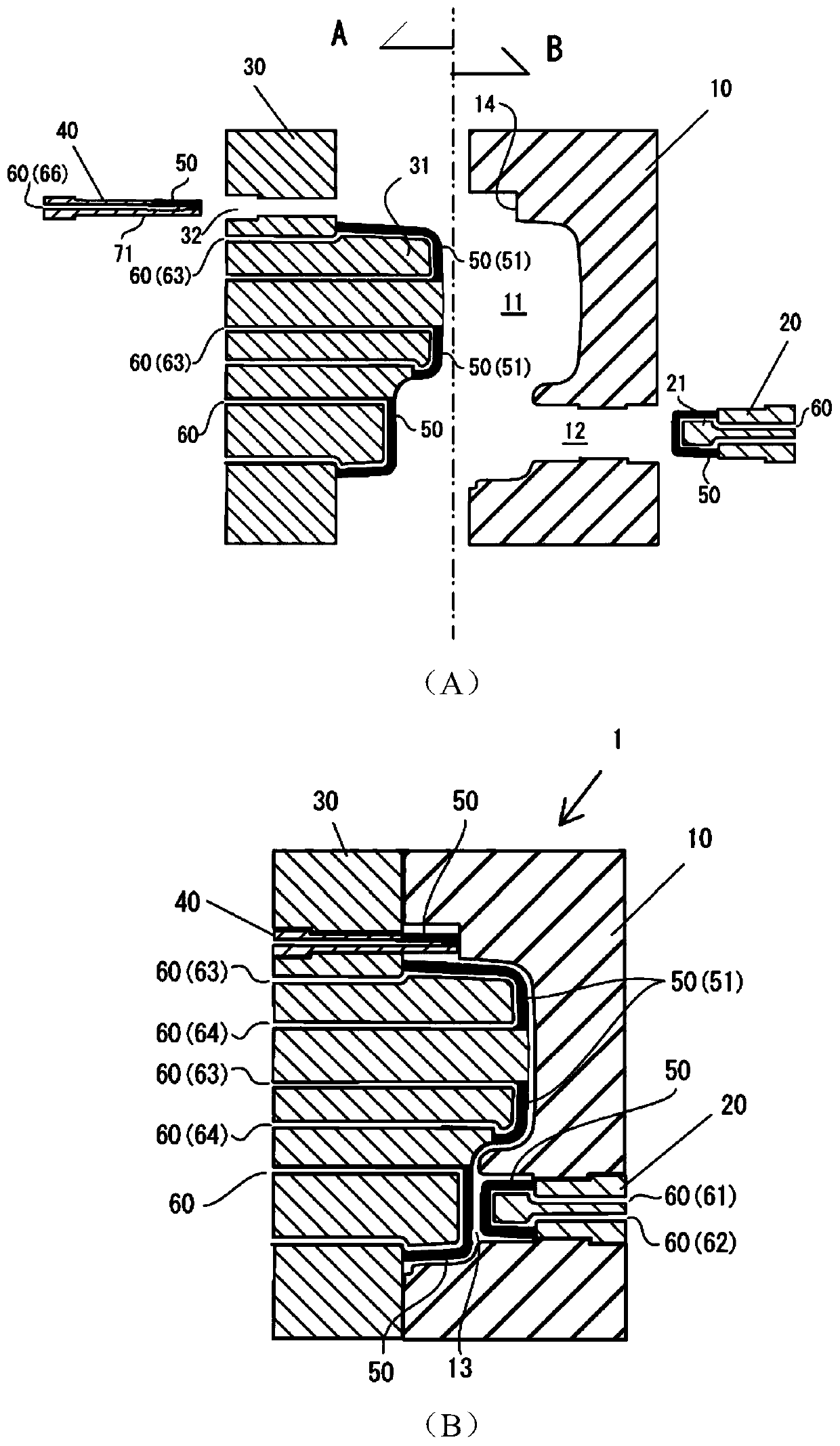
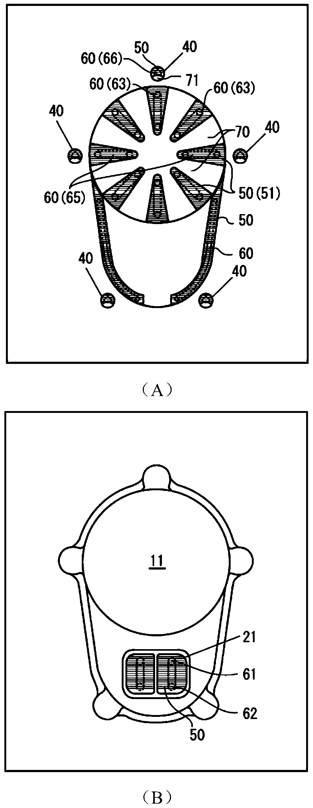
[0076] In the first embodiment, refer to figure 1 , figure 2 , the mold 1 in which the low-density region is formed along the surface of the protruding portion of each inner surface of a pair of molds is described. figure 1 (A) is an explanatory diagram illustrating the structure of the mold through a cross-section, figure 1 (B) is an explanatory diagram illustrating a state in which a pair of molds are brought into contact with each other through a cross section. figure 2 (A) in shows figure 1 A side view of the movable mold viewed from the direction A of (A), figure 2 (B) in shows figure 1 A side view of the fixed mold viewed from the B direction in (A). In addition, in figure 2 In , the phantom line of the liquid path portion is shown by a dotted line.

[0077] The mold 1 of the first embodiment is composed of a fixed mold and a movable mold. The fixed mold is composed of a fixed mold main body 10 and a fixed mold part 20. A concave part 11 is formed in the cen...

no. 2 example

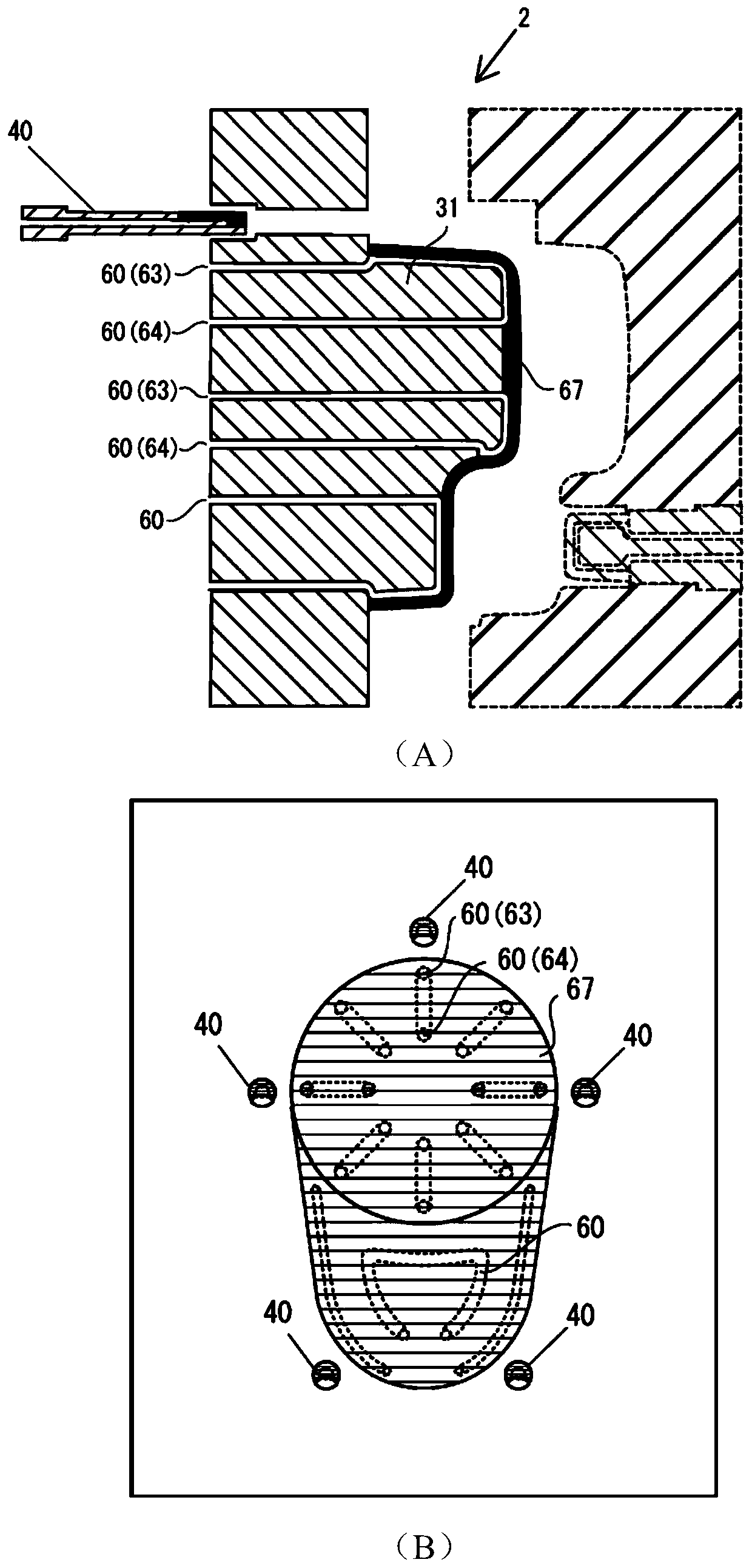
[0092] In the second embodiment, refer to image 3 , the movable mold of the mold 2 in which the low-density region portion is formed in a mode different from that of the first embodiment will be briefly described. image 3 (A) in (A) shows the sectional view of mold 2, image 3 (B) in (B) shows the side view seen from the inner surface of a movable mold. Since the fixed mold can be made the same as the movable mold, only the form of the fixed mold is shown with a dotted line, and description is omitted. In addition, since the liquid path part can be made to be the same as the mold 1 of 1st Example, the same code|symbol is attached|subjected in drawing, and description is abbreviate|omitted.

[0093] The movable mold main body of the mold 2 is the same as the mold 1, and the protruding part 31 is formed so that a step may be formed. The entire peripheral surface of the protruding portion 31 formed to form a step in the movable mold body of the mold 2 is covered with the low...

no. 3 example

[0095] In the third embodiment, referring to Figure 4 , the mold 3 having a structure different from that of the low-density area portion and the liquid path portion on the surface of the front step portion of the protruding portion 31 of the movable mold member of the first embodiment will be described. On the surface of the front step portion of the mold 3, low-density region portions 52 of a predetermined width are arranged along three concentric circles arranged at equal intervals. Figure 4 (A) shows a side view viewed from the inside of the front step portion of the protruding portion of the mold 3, Figure 4 (B) in (B) is an explanatory drawing explaining a liquid path part. Figure 4 (C) in the front step is Figure 4 (A) Explanatory drawing of the cross-sectional view at A position.

[0096] Tubes having a rectangular cross-section in contact with the inner surfaces of the low-density region portions 52 arranged along three concentric circles are disposed so as to...


PUM

PropertyMeasurementUnit
thicknessaaaaaaaaaa

Abstract

To provide a mold that can be brought to a temperature in a predetermined temperature range in a short amount of time, and that is designed to allow the releasing component of a mold releasing agent to be easily spread effectively on an inner surface of the mold, and to reduce the amount of mold releasing agent used. A low-density region of a predetermined thickness is formed along the inner surface of the mold that comes in contact with the molded article, and then, along the inner surface of the mold, a liquid path composed of a hollow tube is formed in contact with the low-density region. It is preferable that a density of the low-density region is higher in a position near an outer surface of the mold than in a position in contact with the liquid path and the low-density region and thehigh-density region are arranged side by side.

Description

technical field [0001] The present invention relates to a mold and a molding system capable of forming molded products with high productivity. In detail, it is related with the mold which suppresses the usage-amount of a mold release agent, and can spread the mold release component of a mold release agent effectively on the inner surface of a mold. More specifically, it relates to a mold in which a low-density region with a predetermined thickness and a liquid path portion forming a hollow tube are formed along the shape of the inner surface of the mold, and the liquid path portion is formed along the low-density region and the low-density region. Partial contact, gas and liquid can flow in the low-density area part and the liquid path part. Background technique [0002] The mold is used as a frame for forming a resin molded product or a metal molded product. In the past, in order to allow the molded product to be released from the mold smoothly, every time the mold was us...

Claims


Application Information

Patent Timeline
Patent Type & Authority Applications(China)
IPC IPC(8): B22D17/20B29C33/60
CPCB22D17/20B29C33/60
Inventor 松冈宽高
Owner SHIPPO KANAGATA INDS
Why Eureka
Try Eureka