Split type oil pressure airtight plunger mud pump convenient in fluid mixing

A liquid mixing and split-type technology, which is applied to components of pumping devices for elastic fluids, liquid variable displacement machinery, variable displacement pump components, etc., can solve potential safety hazards, short device life, easy leakage, etc. problems, to achieve the effect of protecting the safety of use, prolonging the service life and improving the degree of sealing

Inactive Publication Date: 2020-04-24
SHANDONG ZHONGTAN MACHINERY
View PDF0 Cites 0 Cited by
  • Summary
  • Abstract
  • Description
  • Claims
  • Application Information

AI Technical Summary

Problems solved by technology

The plunger, sealing ring, liquid inlet valve and liquid outlet valve of the mud pump work under the conditions of high temperature, high pressure and high speed. The uneven pressure in the pump will cause the service life of these devices to be very short, and most of these parts are Metal material, the surface is easily corroded and worn, and must be replaced regularly, otherwise it is easy to leak and partially fail, causing safety hazards
Therefore, the operation and maintenance costs of the above types of pumps are high. Although people have thought of many ways, they have not been able to fundamentally solve the problem.
[0004] In addition, in the prior art, during the workover of the mud pump oil field, it is often necessary to inject different proportions of mixed oil during the process of cement plugging, sealing channeling, well washing, sand washing and cementing operations, and near and long-distance transportation of crude oil. Mud solution, the existing multi-cylinder mud pump has a fixed stroke, which is not suitable for different use environments, and the actual situation of different requirements for mud solution and mixing requirements

Method used


Image

  • Split type oil pressure airtight plunger mud pump convenient in fluid mixing
  • Split type oil pressure airtight plunger mud pump convenient in fluid mixing
  • Split type oil pressure airtight plunger mud pump convenient in fluid mixing

Examples


Embodiment 1

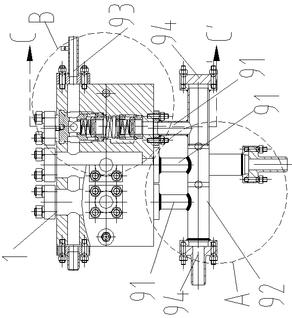
[0051] Example 1. Such as Figure 1-8 As shown, a split oil pressure sealed plunger mud pump that facilitates liquid mixing includes a liquid end 1 and a power end 2 .

[0052] There are several pumping systems between the fluid end 1 and the power end 2.

[0053] Each pumping system includes a valve box assembly, a pull rod installation sleeve 21, and a transmission assembly; each valve box assembly is arranged on the fluid end 1, and each pull rod installation sleeve 21 is arranged on the power end 2; the transmission assembly includes a pull rod 4, a pull rod seal assembly , Plunger 3, plunger seal assembly.

[0054] The valve box assembly includes a valve box body 11, a liquid inlet 12 and a liquid outlet 13 arranged on the side wall of the valve box body 11, and a valve box inner cavity 14 arranged in the valve box body 11; The plunger installation sleeve 15 on the side wall of the valve box body 11 close to the side of the pull rod installation sleeve 21 communicates ...


PUM


Abstract

The invention discloses a split type oil pressure airtight plunger mud pump convenient in fluid mixing. The split type oil pressure airtight plunger mud pump comprises a fluid force end and a power end, wherein a plurality of fluid sucking systems are arranged between the fluid force end and the power end; each fluid sucking system comprises a valve box assembly, a pull rod mounting sleeve and a transmission assembly; each transmission assembly comprises a pull rod, a pull rod sealing assembly, a plunger and a plunger sealing assembly; each pull rod is connected with the corresponding plungerthrough a corresponding adjusting and connecting assembly; each pull rod is mounted on the corresponding pull rod mounting sleeve through the corresponding pull rod sealing assembly; a protecting device is arranged between the end adjacent to each pull rod mounting sleeve, of the corresponding plunger and the corresponding pull rod mounting sleeve; a fluid inlet of each valve box assembly is connected with a corresponding fluid inlet pipe; and a fluid outlet of each valve box assembly is connected with a fluid outlet pipe. Through the adoption of the split type oil pressure airtight plunger mud pump disclosed by the invention, exchanging of single fluid, double fluid and multiple fluid can be realized, the mixing of the fluid of different compounding ratios can be realized, the fluid sucking pump pressure is stable, and the mixing of the fluid is uniform.

Description

technical field [0001] The invention relates to the technical field of pumps, in particular to a plunger mud pump. Background technique [0002] Mud pump is a very important production equipment in the oil field industry and an important part of drilling equipment. It is mainly used for deep well and shallow well operations in oil fields. It can complete water blocking and oil displacement operations to oil wells, and can also be used for cement plugging during oil field workover. , channel sealing, well washing, sand washing and cementing operations, near and long-distance transportation of crude oil and pressure testing, etc. [0003] The plunger of the existing mud pump is made of metal materials. Because the plunger needs to move repeatedly and bear a certain high pressure, the plunger often adopts an integrated structure. Although this structure has good rigidity, pressure resistance and impact resistance, but During manufacture, the precision of the thread on the surf...

Claims


Application Information

Patent Timeline
Patent Type & Authority Applications(China)
IPC IPC(8): F04B15/02F04B53/14F04B53/22F04B53/10F04B49/22
CPCF04B15/02F04B49/22F04B53/10F04B53/14F04B53/143F04B53/147F04B53/22
Inventor 邵丙宏张玉岭邵鹏飞
Owner SHANDONG ZHONGTAN MACHINERY
Why Eureka
Try Eureka