Module switching power supply converter

A switching power supply and converter technology, applied in the field of modular switching power converters, can solve problems such as cumbersome production procedures, reduced market sales scope, unstable production process quality, etc., to reduce labor intensity and production costs, and reduce electrical insulation Problem risk, the effect of expanding the scope of marketing and sales

Inactive Publication Date: 2020-04-24
BEIJING DESIGN TECH
View PDF0 Cites 0 Cited by
  • Summary
  • Abstract
  • Description
  • Claims
  • Application Information

AI Technical Summary

Problems solved by technology

It is difficult to meet the existing structural packaging methods for metal shell module power supplies where the PCBA cannot be fastened with screws in the metal shell, the fixing accuracy of the tooling is poor, the production process is cumbersome, and the cost is high. It is also not suitable for batch flow operation
[0003] Problems and shortcomings of existing technical solutions: unstable production process quality, poor assembly and processing performance; limited development space and batch production operations of power modules; unable to meet the needs of module power supplies with high pin and shape packaging accuracy; Lean production, high efficiency, and consistent quality requirements cannot be satisfied by the power supply at the same time
Only low-end power modules with lower requirements or fewer production quantities can be applied, which reduces the scope of market sales, and has high labor intensity, low efficiency, complicated operation, and high cost

Method used


Image

  • Module switching power supply converter
  • Module switching power supply converter

Examples


Embodiment Construction

[0018] The following will clearly and completely describe the technical solutions in the embodiments of the present invention with reference to the accompanying drawings in the embodiments of the present invention. Obviously, the described embodiments are only some, not all, embodiments of the present invention. Based on the embodiments of the present invention, all other embodiments obtained by persons of ordinary skill in the art without making creative efforts belong to the protection scope of the present invention.

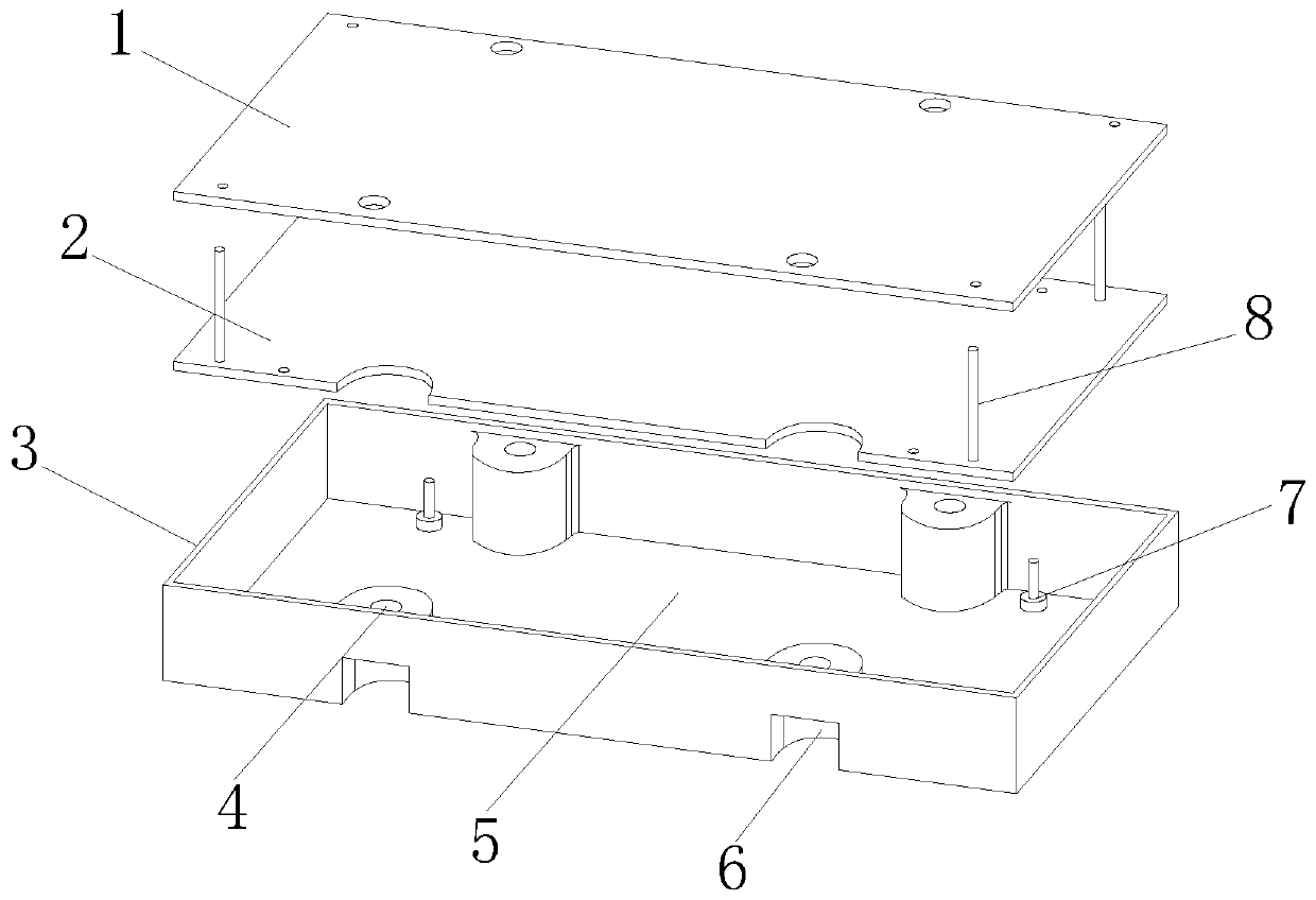
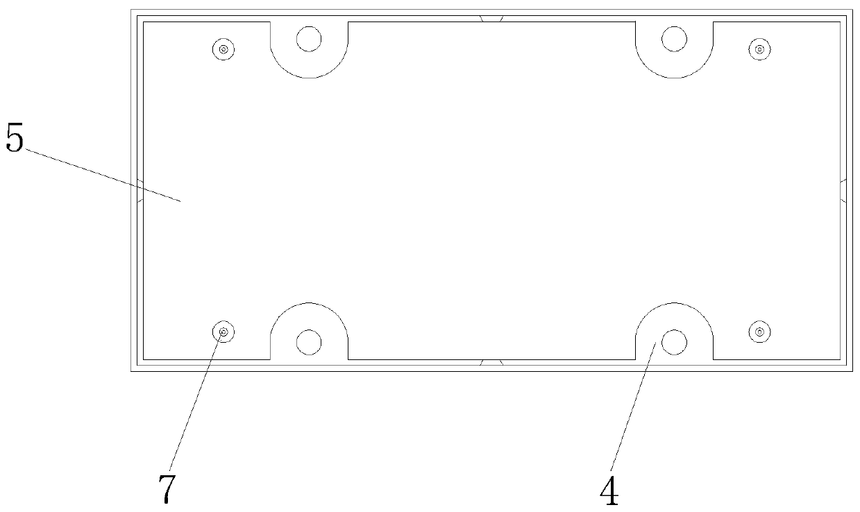
[0019] see Figure 1-2 , the present invention provides the following technical solutions: a modular switching power supply converter, including a cover plate 1, a power supply printed board 2, a metal shell 3, an insulating sheet 5 and a riveted copper needle 7, and the inner two ends of the metal shell 3 are arranged The limit support frame 4, in order to improve the structural stability, the limit support frame 4 is set as a semi-cylindrical structure, the ...


PUM


Abstract

The invention discloses a module switching power supply converter which comprises a cover plate, a power supply printed board, a metal shell, an insulating sheet and riveting copper needles. Limitingsupporting frames are arranged at the two ends of the interior of the metal shell, the riveting copper needles are arranged on the side edges of the limiting supporting frames, and the insulating sheet is arranged at the bottom of the metal shell. The problems of poor operability, low production efficiency and poor quality stability for shape positioning machining of in-shell packaging of a powersupply printed board are solved; the layout space of an in-shell power supply printed board device is increased, and the risk of electrical insulation is reduced; the cost of additionally arranging the riveting needles in the new structure shell design is lower than the labor and tool cost of production operation; the appearance quality and the relative position quality of the pins are improved, so that the risk of compact application space of the client is also reduced; flying wire grounding is canceled, so that the labor intensity and the production cost are reduced, the production efficiency is improved, the risk of flying wire desoldering is greatly reduced, and the appearance quality after welding is optimized; and the market sales range is expanded.

Description

technical field [0001] The invention belongs to the technical field of power converters, and in particular relates to a modular switching power converter. Background technique [0002] Modular switching power supply converter is a widely used power supply module. At present, there are power supply products for this application. The modular switching power supply is packaged in a metal shell that requires heat dissipation and shielding. Its usual structure is designed as a printed board PCBA+machined metal shell. Or stretch metal shell + potting glue + welded bottom cover or viscose fixed shield cover. The power printed circuit board PCBA is mainly positioned and fixed through process tooling positioning + potting glue. For example, the PCBA needs to be grounded with the metal shell, and the process package needs to be connected to the metal shell with a separate flying wire. It is difficult to meet the existing structural packaging methods for metal shell module power suppl...

Claims


Application Information

Patent Timeline
Patent Type & Authority Applications(China)
IPC IPC(8): H02M1/00
CPCH02M1/00
Inventor 彭云辉
Owner BEIJING DESIGN TECH
Why Eureka
Try Eureka