Adjusting device for a cutting tool and cutting tool having an adjusting device

A technology of cutting tools and cutting tools, which is applied in the direction of tool holders, manufacturing tools, mechanical equipment, etc., can solve the problems of endangering the accuracy of cutting tools or the stability of diameter and size, and achieve the effect of high diameter and size stability

Active Publication Date: 2020-04-24
钴领两合公司
View PDF4 Cites 0 Cited by
  • Summary
  • Abstract
  • Description
  • Claims
  • Application Information

AI Technical Summary

Problems solved by technology

However, movement or vibration of the cutting edge carrier compromises the desired high feed accuracy or diameter dimensional stability of the cutting tool

Method used


Image

  • Adjusting device for a cutting tool and cutting tool having an adjusting device
  • Adjusting device for a cutting tool and cutting tool having an adjusting device
  • Adjusting device for a cutting tool and cutting tool having an adjusting device

Examples


Embodiment approach

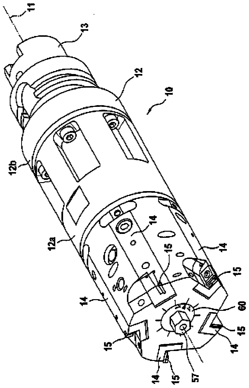
[0031] figure 1 A perspective side view of a multi-edged cutting tool 10 , for example for machining cylinder bores of internal combustion engines, is shown. Thus, the cutting tool 10 may be referred to as a cylinder bore machining tool or generally as a drilling remachining tool or a drilling finishing tool.

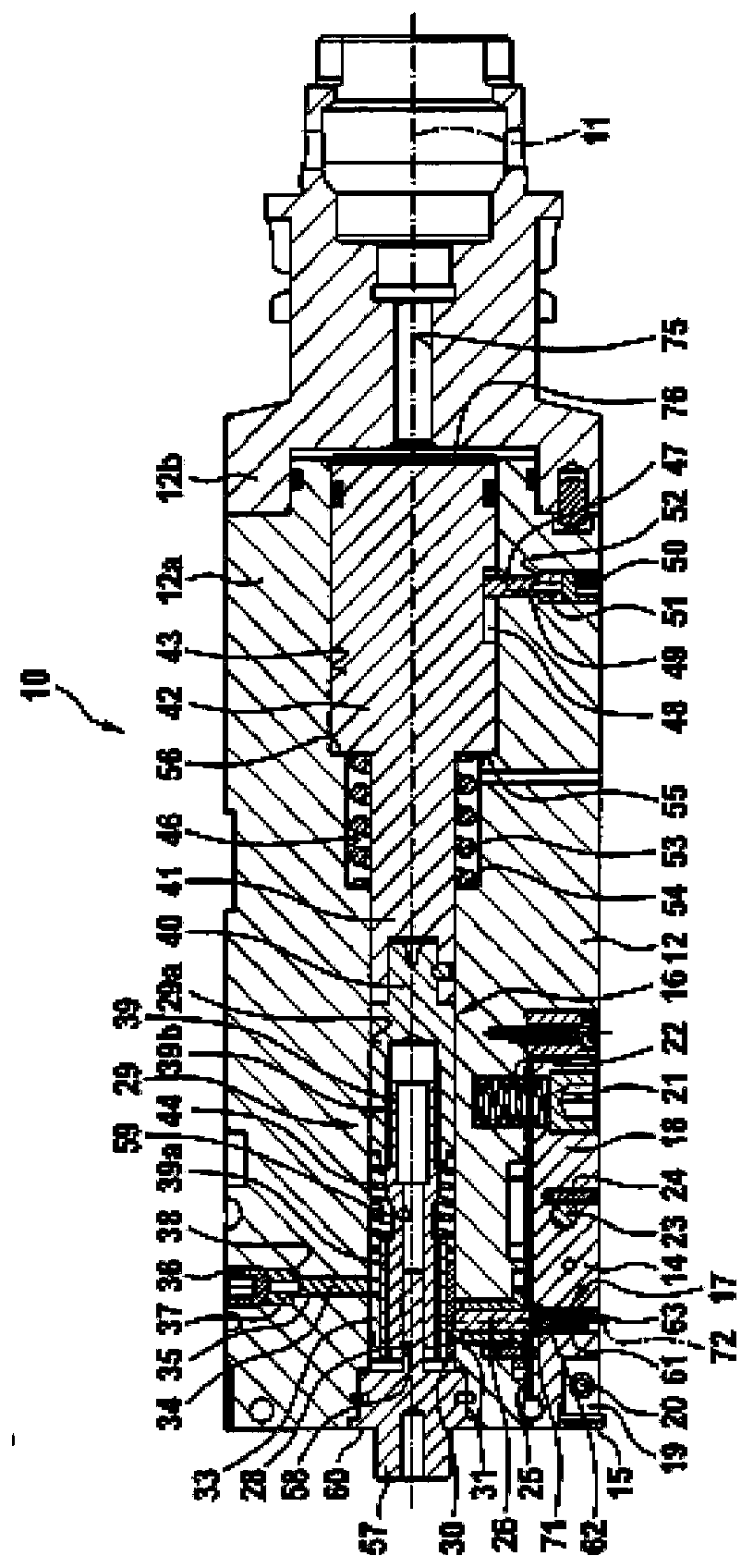
[0032] The cutting tool 10 has a base body 12 extending along a longitudinal center axis or axis of rotation 11 , which in the embodiment shown is modularly formed from a front part and a rear part. like figure 1 As shown, the front portion 12a and the rear portion 12b are screwed to each other. The cutting tool 10 is at its rear end ( figure 1 There is a coupling shank 13 to be connected to eg a machine tool spindle, which in the embodiment shown is formed by a HSK (Hollow Shaft Taper) shank. Alternatively, however, it is also possible, for example, to provide a so-called SK (steep taper) shank or the like. The cutting tool 10 can be used stationary or driven in r...


PUM


Abstract

The invention relates to an adjusting device 17 for the fine adjustment of a blade carrier 14 held in a settable manner on a main body 12 of a cutting tool 10 relative to the main body 12, having an adjusting screw 63 that determines the position of the blade carrier 14 with respect to the main body 12. The adjusting device 17 comprises a threaded bush 61 with which the adjusting screw 63 is screwed together and which has a wall segment 66 that is elastically deformable transversely to the bush axis 70, and a pressure element 64 that is arranged to the side of the threaded bush 61 and pressesthe wall segment 66 against the adjusting screw 63.

Description

technical field [0001] The invention relates to an adjustment mechanism for fine adjustment of a fine adjustment of a cutting edge carrier held adjustably on a base body of a cutting tool, and to a cutting tool having such an adjustment mechanism. Background technique [0002] Especially when it comes to maintaining tight diameter tolerances of the bore, an adjustment mechanism for fine adjustment of the cutting edge carrier held adjustably on the base body of the cutting tool is used. For example, DE 4022579 A1 shows and describes a cutting tool with a base body that can be driven in rotation about an axis of rotation and a cutting edge carrier arranged radially adjustable on the base body and carrying the cutting tool. The cutting edge carrier is embodied as a double-armed pivot beam, which is pivotably arranged in a pivot bearing oriented transversely to the axis of rotation in the base body with radial adjustment of the cutting tool arranged on one lever arm of the pivot...

Claims


Application Information

Patent Timeline
IPC IPC(8): B23B29/034F16B39/02
CPCB23B29/0341B23B29/03446F16B39/028B23B2260/056B23B2270/06B23B29/205B23B29/03417B23B29/03435
Inventor G·黑克尔H-P·豪费德J·塔纳
Owner 钴领两合公司
Why Eureka
Try Eureka