[0021] In order to make the above-mentioned objects, features and advantages of the present invention more obvious and understandable, the specific embodiments of the present invention will be described in detail below with reference to the accompanying drawings. In the following description, many specific details are explained in order to fully understand the present invention. However, the present invention can be implemented in many other ways different from those described herein, and those skilled in the art can make similar improvements without departing from the connotation of the present invention. Therefore, the present invention is not limited by the specific implementation disclosed below.
[0022] It should be noted that when an element is referred to as being "fixed to" another element, it can be directly on the other element or a central element may also exist. When an element is considered to be "connected" to another element, it can be directly connected to the other element or an intermediate element may be present at the same time. The terms "vertical", "horizontal", "left", "right" and similar expressions used herein are for illustrative purposes only, and are not meant to be the only embodiments.
[0023] Unless otherwise defined, all technical and scientific terms used herein have the same meaning as commonly understood by those skilled in the technical field of the present invention. The terms used in the specification of the present invention herein are only for the purpose of describing specific embodiments, and are not intended to limit the present invention. The term "and/or" as used herein includes any and all combinations of one or more related listed items.
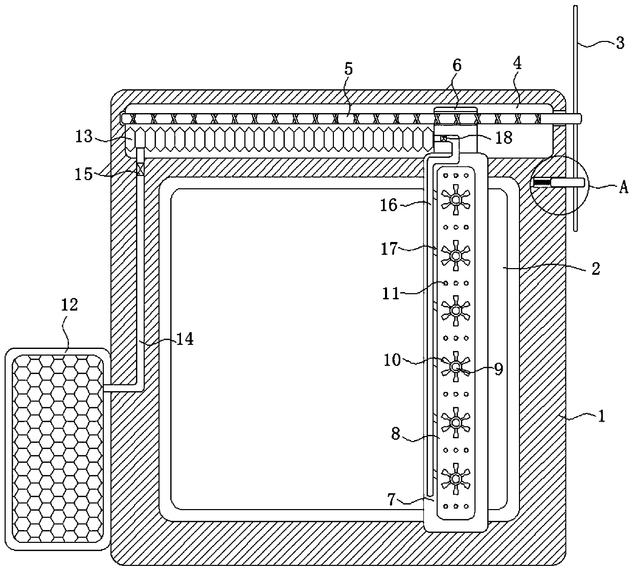
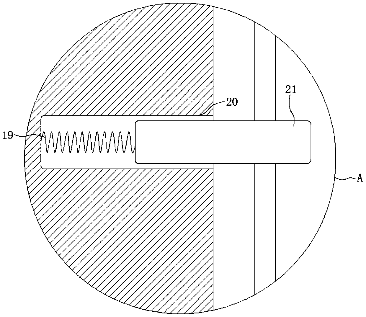
[0024] Reference Figure 1-4 , A solar photovoltaic panel dust cleaning equipment, including a mounting frame 1 with an inclined upper surface, a photovoltaic panel 2 is provided at the upper end of the mounting frame 1, a groove 4 is opened at the upper end of the mounting frame 1, and a reciprocating wire is rotatably connected to the side wall of the groove 4 A plurality of fan blades 3 are fixedly connected to the end of the rod 5 and the reciprocating screw 5 away from the side wall of the groove 4, and the blades of the fan blade 3 are relatively large to ensure that the fan blade 3 can be driven to rotate under the action of the wind. The wall is provided with a sliding groove 20. The inner wall of the sliding groove 20 is elastically connected with a pin 21 through a memory spring 19. The memory spring 19 is made of a nickel-titanium memory alloy material. The transformation temperature of the nickel-titanium memory alloy is 40°C. When the temperature reaches the transformation temperature of the nickel-titanium memory alloy, it will deform into a contracted state. When the external temperature is lower than the transformation temperature of the nickel-titanium memory alloy, it will deform into a stretched state, and the external temperature will rise to the memory spring at noon At the abnormal temperature of 19, the memory spring 19 will contract, driving the latch 21 to separate from the fan blade 3, such as Figure 4 It shows that the fan blade 3 is no longer restricted, and the fan blade 3 will rotate under the action of wind.
[0025] It should be noted that the temperature in winter is low, and the noon sun is not enough to make the memory spring 19 reach the abnormal temperature. At this time, the memory spring 19 and the plug 21 can be embedded in the power generation components of the photovoltaic panel 2. The heat is enough to make the memory spring 19 reach the metamorphic temperature, thereby cleaning the surface dust of the photovoltaic panel 2.
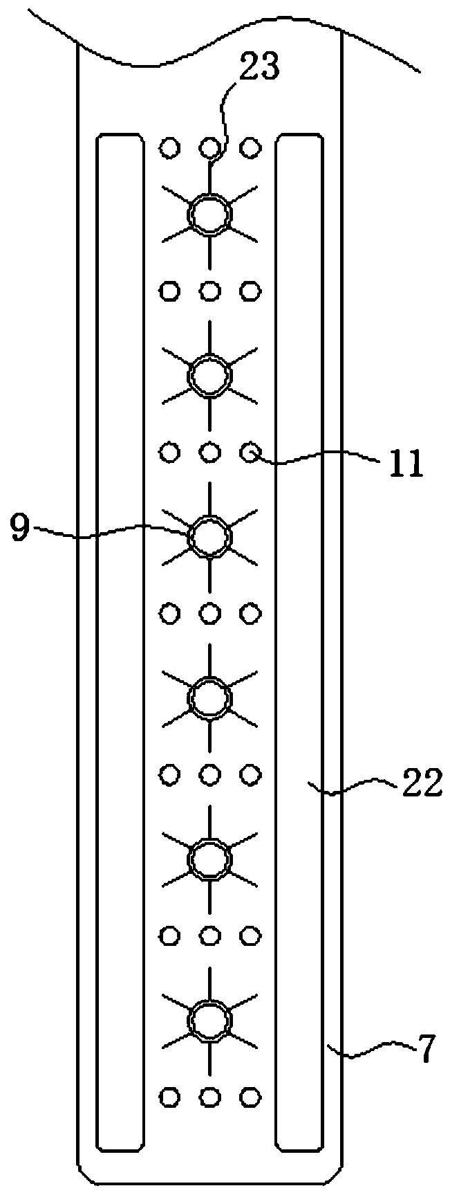
[0026] A cleaning device for cleaning the surface of the photovoltaic panel 2 is installed on the horizontal plate 7. The cleaning device includes bristles 23. The horizontal plate 7 is provided with a cavity 8 and the side wall of the horizontal plate 7 is connected with a plurality of centers communicating with the inner wall of the cavity 8. The hollow tube 9, the side walls of the hollow tubes 9 in the cavity 8 are uniformly distributed and fixedly connected with a plurality of impellers 10, and the rotation of the plurality of impellers 10 will drive the bristles 23 to rotate to clean up the stubborn substances on the surface of the photovoltaic panel 2. Avoid stubborn substances adhering to the surface of the photovoltaic panel 2. When the photovoltaic panel 2 forms a shadow under the sun, the hot spot effect is generated. The bristles 23 are evenly distributed and fixedly connected to the side wall of the hollow tube 9 away from the impeller 10, and the impeller 10 approaches The inner wall of the cavity 8 is arranged so that the nozzle of the hollow tube 9 and the inner wall of the cavity 8 are almost kept horizontal, so that the rainwater can flow out of the nozzle of the hollow tube 9 after entering the cavity 8 without being in the cavity 8 After being accumulated, it flows out from the nozzle of the hollow tube 9. The side wall of the horizontal plate 7 is symmetrically connected with a cleaning strip 21. The cleaning strip 21 is attached to the surface of the photovoltaic panel 2, which can not only clean the dust on the surface of the photovoltaic panel 2, but also The water stains on the surface of the photovoltaic panel 2 are scraped off to avoid the water stains remaining on the surface of the photovoltaic panel 2, and the water stains evaporate under the sunlight to form a light spot, which leads to the generation of a hot spot effect. The side walls of the horizontal plate 7 are provided with multiple The water outlet hole 11 connected with the inner wall of the cavity 8 can make rain water quickly wet the dust on the surface of the photovoltaic panel 2 through the water outlet hole 11, so as to perform rapid cleaning under the action of the bristles 23. The entire cleaning device is made of transparent material This effectively avoids shielding the surface of the photovoltaic panel 2 during the cleaning process of the surface of the photovoltaic panel 2 so that the heated temperature of the silicon wafers inside the photovoltaic panel 2 is uneven, thereby generating a hot spot effect.
[0027] The side wall of the mounting frame 1 is fixedly connected with a water tank 12, and a filter plate is fixedly connected in the water tank 12. The filter plate can block some fallen leaves and other debris above the water tank 12 to avoid blockage in the water inlet tank 12, thereby affecting the water tank 12. The mounting frame 1 is equipped with a pumping device for pumping the water in the water tank 12 into the cavity 8. The pumping device includes a telescopic airbag 13 fixedly connected to the side wall of the groove 4, and the groove 4 is notched. The sun visor can prevent the telescopic airbag 13 from aging under long-term sunlight and extend its service life. The end of the telescopic airbag 13 away from the side wall of the groove 4 is fixedly connected with the side wall of the slider 6, and the side wall of the water tank 12 is provided with The water inlet cavity 14 connected with the telescopic airbag 13 is located on the side wall of the mounting frame 1. The water inlet cavity 14 is installed with a first one-way valve 15 that only allows water to enter the telescopic airbag 13 from the water tank 12. The side wall of the plate 7 is provided with a water outlet chamber 16 communicating with the telescopic airbag 13. The water outlet chamber 16 is equipped with a second one-way valve 18 that only allows water to enter the water outlet chamber 16 from the telescopic airbag 13 and the inner wall of the cavity 8 is provided with multiple The water spray holes 17 communicated with the inner wall of the water outlet chamber 16, and a plurality of water spray holes 17 are arranged obliquely toward the direction of the impeller 10. As the area of the inner chamber of the telescopic airbag 13 is large, and the aperture of the water outlet chamber 16 is small, the telescopic airbag 13 The rainwater inside can be quickly sprayed from the water spray hole 17 to produce a large tangential force on the impeller 10, thereby driving the impeller 10 to rotate quickly, so that the bristles 23 rotate quickly, and the bristles 23 quickly rotate to ensure that stubborn dust is cleaned. , To avoid the hot spot effect caused by some stubborn dust that has not been cleaned. At the same time, the high noon temperature will reduce the heat dissipation efficiency of the photovoltaic panel 2. The water spray cleaning can also cool the photovoltaic panel 2 and improve the power generation efficiency when the noon temperature is too high.
[0028] In the present invention, when the outside temperature rises at noon and reaches the metamorphic temperature of the memory spring 19, the memory spring 19 shrinks, driving the latch 21 to slide away from the fan blade 3, so that the latch 21 moves from between the two fan blades 3. When the gap is separated, due to the large blades of the fan blade 3, the fan blade 3 will rotate under the action of external wind, and then drive the reciprocating screw 5 to rotate, causing the slider 6 to move back and forth on the reciprocating screw 5, thereby driving The horizontal plate 7 slides back and forth on the surface of the photovoltaic panel 2, and the dust on the surface of the photovoltaic panel 2 is cleaned by the cleaning strip 21 and the bristles 23 on the side wall of the horizontal plate 7.
[0029] Since the slider 6 and the side wall of the groove 4 are fixedly connected to the telescopic airbag 13, when the slider 6 moves to the side close to the fan blade 3, the telescopic airbag 13 will be stretched, so that there is a negative pressure in the telescopic airbag 13 and the water tank The rainwater in 12 flows into the telescopic airbag 13 through the water inlet cavity 14. When the slider 6 moves to the side away from the telescopic airbag 13, the telescopic airbag 13 will be compressed, so that there is a positive pressure in the telescopic airbag 13, thereby causing the expansion and contraction. The water in the airbag 13 is squeezed and flows into the water outlet chamber 16, and is quickly sprayed from the spray hole 17. As the spray hole 17 is inclined to the direction of the impeller 10, the rainwater sprays from the spray hole 17 on the impeller. 10 generates a large tangential force, which in turn makes the impeller 10 rotate quickly, so that the bristles 23 rotate quickly, moisturizing and scraping the stubborn dust on the surface of the photovoltaic panel 2, and when the horizontal plate 7 moves back and forth, it will clean The strip 21 scrapes and cleans the water stains on the surface of the photovoltaic panel 2.
[0030] When the external temperature gradually drops below the metamorphic temperature of the memory spring 19, the memory spring 19 will be stretched to a stretched state, pushing the latch 21 to slide closer to the fan blade 3, so that the latch 21 is inserted into the adjacent two fan blades 3 At the gap, the rotation of the fan blade 3 is limited, so that the fan blade 3 cannot continue to rotate under the action of the wind.
[0031] The above are only preferred specific embodiments of the present invention, but the protection scope of the present invention is not limited to this. Anyone familiar with the technical field within the technical scope disclosed by the present invention, according to the technical solution of the present invention Equivalent replacements or changes to its inventive concept should all fall within the protection scope of the present invention.