A continuous forming method for low melting point metal

A technology of low melting point metal and forming method, applied in the field of metal forming, can solve the problems of difficult continuous forming and strong surface tension of low melting point metal, and achieve the effects of easy recovery, convenient extraction and continuous forming

Active Publication Date: 2022-02-22
BEIHANG UNIV
View PDF9 Cites 0 Cited by
  • Summary
  • Abstract
  • Description
  • Claims
  • Application Information

AI Technical Summary

Problems solved by technology

[0009] The purpose of the present invention is to provide a continuous forming method of low melting point metal, which is simple, easy to operate, and can effectively solve the problem that the low melting point metal has a strong surface tension and is difficult to continuously form

Method used


Image

  • A continuous forming method for low melting point metal
  • A continuous forming method for low melting point metal
  • A continuous forming method for low melting point metal

Examples


Embodiment 1

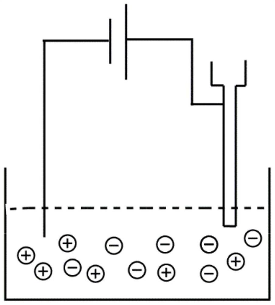
[0039] The forming method process of low melting point metal is as follows:

[0040] (1) Prepare 1mmol / L NH 4 Cl solution is used as conductive matrix liquid;

[0041] (2) Heating to melt the indium-based alloy into a liquid state;

[0042] (3) Turn on the power to make the NH prepared in step (1) 4 The Cl solution is energized, and the control voltage is 50V;

[0043] (4) Turn on the injection device, and uniformly inject the molten indium-based alloy obtained in step (2) into NH at an extrusion speed of 50 μL / min. 4In the Cl solution, the injection head of the injection device is controlled to move at a constant speed during the injection process, and the moving speed is controlled to be 25mm / s, so that in NH 4 Continuous indium-based alloy wires are formed in Cl solution.

Embodiment 2

[0045] The forming method process of low melting point metal is as follows:

[0046] (1) Prepare 5mol / L NaCl solution as conductive matrix solution;

[0047] (2) Heating to melt the gallium-based alloy into a liquid state;

[0048] (3) Turn on the power to energize the NaCl solution prepared in step (1), and control the voltage to 1.5V;

[0049] (4) Turn on the injection device, and uniformly inject the molten gallium-based alloy obtained in step (2) into the NaCl solution at an extrusion speed of 600 μL / min, and control the injection head of the injection device to move at a constant speed during the injection process. The speed is controlled to be 50mm / s, so that a continuous gallium-based alloy metal wire is formed in the NaCl solution.

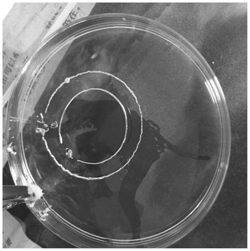
[0050] After forming, the gallium-based alloy metal wire taken out from the NaCl solution is as follows: figure 2 As shown, the obtained metal lines are continuous and uniform, and there is no black oxide layer on the surface.

Embodiment 3

[0052] The forming method process of low melting point metal is as follows:

[0053] (1) Prepare 10mol / L conductive gel solution as conductive matrix solution;

[0054] (2) Heating to melt the tin-based alloy into a liquid state;

[0055] (3) Turn on the power to energize the conductive gel solution prepared in step (1), and control the voltage to 20V;

[0056] (4) Turn on the injection device and uniformly inject the molten tin-based alloy obtained in step (2) into the conductive gel solution at an extrusion speed of 800 μL / min, and control the injection head of the injection device to move at a constant speed during the injection process , the moving speed is controlled to be 100mm / s, thereby forming continuous tin-based alloy metal wires in the conductive gel liquid.


PUM

PropertyMeasurementUnit
melting pointaaaaaaaaaa

Abstract

The invention discloses a continuous molding method for low-melting-point metals, which uniformly injects liquid low-melting-point metals into a neutral conductive matrix liquid in an electrified state, and controls the injection head to move at a constant speed during the injection process, and the moving speed is controlled 5-100mm / s, so that the liquid low melting point metal forms a continuous metal in the conductive matrix liquid. The method is simple and easy to operate, and can effectively solve the problem that the low melting point metal has a strong surface tension and is difficult to form continuously.

Description

technical field [0001] The invention belongs to the technical field of metal forming, and in particular relates to a continuous forming method of low melting point metal. Background technique [0002] Low-melting point metals / alloys refer to metals and their alloys with a melting point below 300°C, generally 60-200°C. Low melting point metals include bismuth, tin, lead, indium, gallium, rubidium, and cesium, among others. These metals are also called liquid metals because they have a low melting point and easily transform into a fluid form when heated. [0003] This kind of metal has the characteristics of low melting point, strong electrical conductivity, and strong fluidity. It can be used in the preparation and repair of various deformed devices, and has been widely used in medical, electronic and other fields. [0004] However, after research and experiments, it was found that this kind of liquid metal often forms a spherical droplet state due to its strong surface ten...

Claims


Application Information

Patent Timeline
Patent Type & Authority Patents(China)
IPC IPC(8): B22F3/22
CPCB22F3/225
Inventor 胡靓王新鹏
Owner BEIHANG UNIV
Why Eureka
Try Eureka