
Macroscopic metallographic shooting analysis device for pipeline circumferential weld and using method thereof

An analysis device and technology for girth welds, which are applied in the field of macro metallographic photographing and analysis devices for pipeline girth welds, can solve the problems of poor macro metallographic image quality, poor light source conditions, inaccurate results, etc., so as to avoid image reflection and ensure Stability, clear and beautiful appearance of weld seam

Pending Publication Date: 2020-04-28
BC P INC CHINA NAT PETROLEUM CORP +1
View PDF0 Cites 2 Cited by
  • Summary
  • Abstract
  • Description
  • Claims
  • Application Information

AI Technical Summary

Problems solved by technology

[0004] During laboratory inspection, because there is no suitable macroscopic metallographic shooting device, the testers often use mobile phones or digital cameras to take pictures. The light source conditions are relatively poor and the image quality is uneven; For quantitative measurement and description, it is also necessary to measure the defect size with the help of an optical metallographic microscope
Therefore, the quality of the macroscopic metallographic picture of the girth weld obtained by the prior art is poor, and the result is inaccurate; when there is a welding defect, it is sometimes necessary to use an optical microscope for analysis, which is time-consuming and laborious

Method used


Image

  • Macroscopic metallographic shooting analysis device for pipeline circumferential weld and using method thereof
  • Macroscopic metallographic shooting analysis device for pipeline circumferential weld and using method thereof
  • Macroscopic metallographic shooting analysis device for pipeline circumferential weld and using method thereof

Examples


Embodiment Construction

[0037] In order to make the purpose, technical solutions and advantages of the embodiments of the present invention clearer, the technical solutions of the present invention will be clearly and completely described below in conjunction with the accompanying drawings. Obviously, the described embodiments are part of the embodiments of the present invention, not all of them. the embodiment. Based on the embodiments of the present invention, all other embodiments obtained by persons of ordinary skill in the art without making creative efforts belong to the protection scope of the present invention.

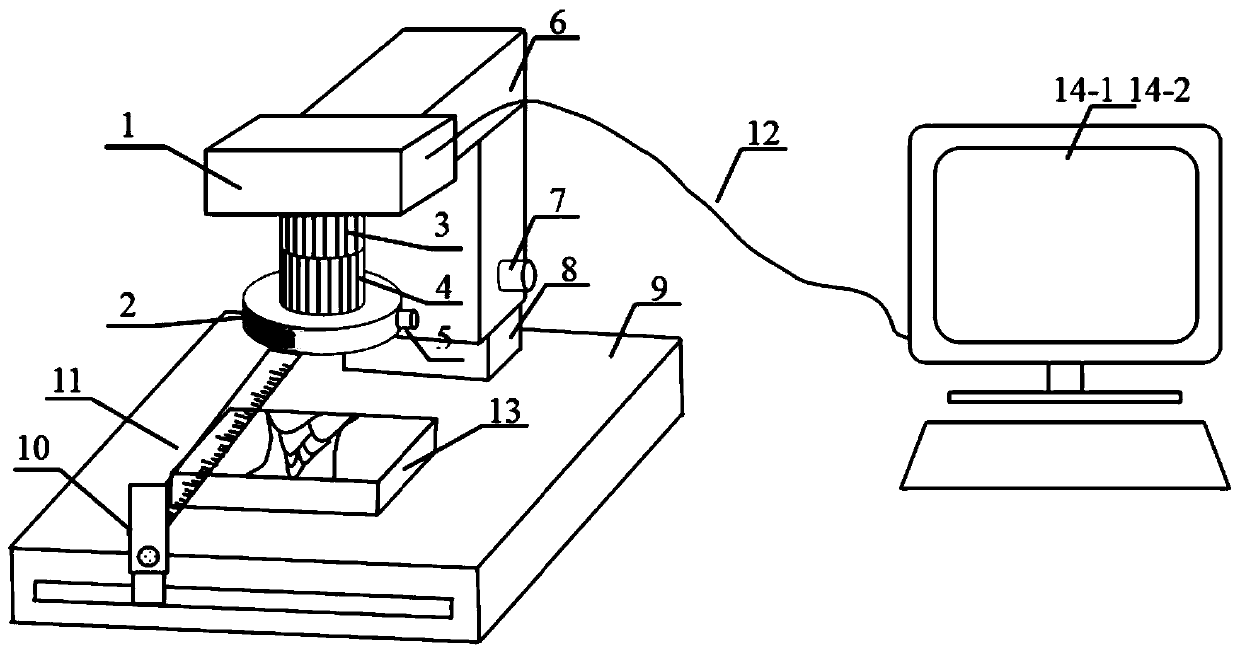
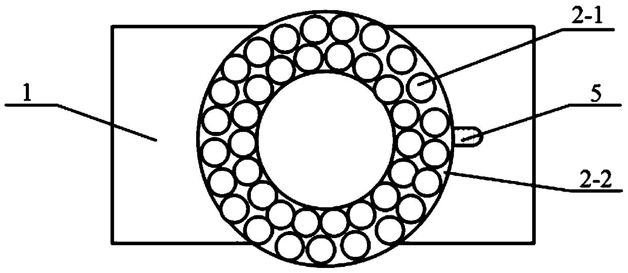
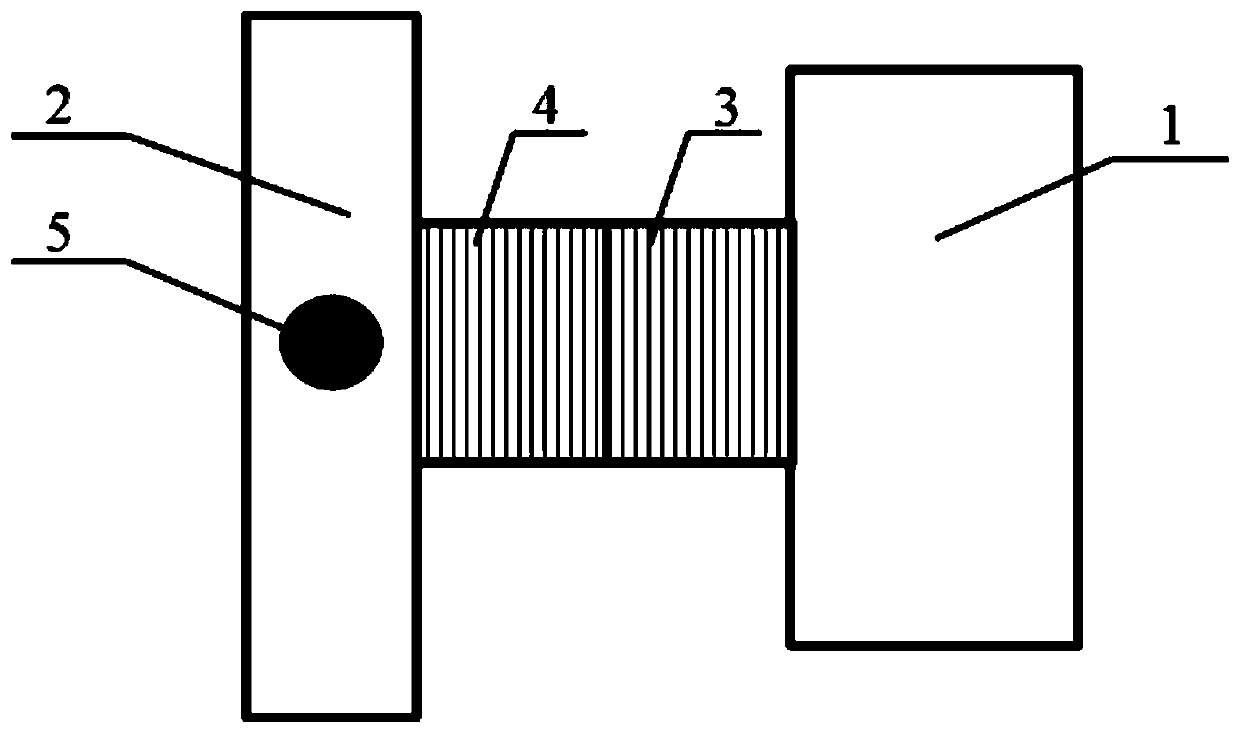
[0038] Such as figure 1 As shown, as a specific embodiment of the present invention, a macroscopic metallographic photographing and analysis device for pipeline girth welds includes an image acquisition device 1, a soft lighting system 2, a measuring scale 11, an image processing module 14-1, an image The measuring module 14-2 and the fixing frame, the image acquisition device 1 in ...


PUM


Abstract

The invention discloses a macroscopic metallographic shooting analysis device for a pipeline circumferential weld and a using method thereof. An image acquisition device is fixed on a fixing frame; afocusing knob and an amplification factor adjusting knob are arranged on the image acquisition device; a soft light illumination system is arranged on the outer ring of the bottom end of a lens of theimage acquisition device; and a measuring scale is arranged at the position, where a to-be-detected weld joint sample is placed, on the fixing frame. The image acquisition device is used for acquiring image information of a to-be-detected weld joint sample and sending collected image information to an image processing module; the image processing module is used for carrying out brightness adjustment, contrast enhancement processing and weld joint fusion line contour extraction on the received image information and sending the processed image information to an image measurement module; and theimage measurement module is used for measuring the defect size in a weld joint. According to the invention, the high-quality macroscopic metallographic picture of the circumferential weld can be quickly obtained, the defect size and the like in the welded joint can be directly inspected and measured, and the inspection result is accurate and reliable.

Description

technical field [0001] The invention belongs to the field of weld metallographic detection, and in particular relates to a macroscopic metallographic photographing and analysis device for pipeline girth welds and a use method thereof. Background technique [0002] As an economical, safe and continuous transportation method, long-distance pipelines have been widely used in the transportation of oil, natural gas and liquid slurry. For long-distance oil and gas transmission pipeline projects, steel pipes are usually connected by on-site welding (butt girth weld). Because the existence of girth welds destroys the structural integrity of long-distance pipelines, pipeline failure accidents occur frequently. Therefore, pipeline owners and construction parties pay more and more attention to the welding process and quality of pipeline girth welds. [0003] The macroscopic metallographic analysis test of the girth weld weld joint is a means to evaluate the welding process and weldin...

Claims


Application Information

Patent Timeline
IPC IPC(8): G01N21/88G01B11/00G01N21/01
CPCG01N21/88G01B11/00G01N21/01
Inventor 仝珂樊治海瞿婷婷白小亮何小东陈志昕
Owner BC P INC CHINA NAT PETROLEUM CORP
Learn More