
Foundation settlement monitoring system based on laser measurement

A technology of foundation settlement and monitoring system, applied in the field of building detection, can solve problems such as poor real-time performance, inaccurate results, and untimely monitoring, and achieve the effect of mature design method, simple principle and reliable operation.

Inactive Publication Date: 2020-05-01
ANHUI UNIV OF SCI & TECH
View PDF8 Cites 5 Cited by
  • Summary
  • Abstract
  • Description
  • Claims
  • Application Information

AI Technical Summary

Problems solved by technology

Due to the limited monitoring scope and the constraints of traffic and hydrogeological conditions, the implementation of large-scale building settlement monitoring is difficult, and the monitoring is not timely, resulting in an incomplete safety assessment of large-scale man-made buildings.
[0004] The invention discloses a foundation settlement monitoring system based on laser measurement. The laser is transmitted in a straight line, and the displacement detection of the laser light spot is carried out in a non-contact manner, which mainly solves the inconvenient and inaccurate detection of the continuous settlement of the existing foundation. , The real-time problem is not strong

Method used


Image

  • Foundation settlement monitoring system based on laser measurement
  • Foundation settlement monitoring system based on laser measurement
  • Foundation settlement monitoring system based on laser measurement

Examples


Embodiment Construction

[0015] Below by specific embodiment and in conjunction with accompanying drawing, the present invention is further explained and illustrated:

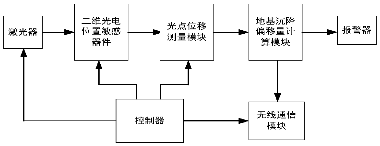
[0016] Such as figure 1 As shown, it is a system structure diagram of the present invention, and the foundation settlement monitoring method using laser measurement includes the following parts: controller, laser, two-dimensional light spot position sensitive device, light spot displacement measurement module, foundation settlement offset calculation module, wireless communication module. The controller controls the functions of each module of the entire monitoring system; the laser provides a laser tube light source that propagates in a straight line; the two-dimensional light spot position sensitive device receives the laser light spot signal; the light spot displacement detection module calculates the cheapness of the laser light spot; The displacement data of light spots received by each monitoring point calculates the offset of f...


PUM


Abstract

The invention discloses a foundation settlement monitoring system based on laser measurement, which mainly solves the problems of inconvenience, inaccurate result and poor real-time performance of theconventional foundation continuous settlement detection. The foundation settlement monitoring system mainly consists of controllers, lasers, two-dimensional photoelectric position sensitive devices,photoelectric displacement measuring modules, foundation settlement offset calculating modules, wireless communication modules and alarms. The foundation settlement monitoring system is characterizedin that: two or more monitoring points are arranged in areas with different geological conditions in space, each monitoring point is provided with a set of laser transmitting and receiving equipment,and the controller is used for measuring laser spot displacement parameters between the monitoring points and sending the laser spot displacement parameters to the controllers on other monitoring points through the wireless communication module; each monitoring point is provided with a laser emitter and a laser spot displacement detection circuit, and the monitoring points work intermittently, sothat the purpose of saving power consumption is achieved; and when a settlement value exceeds a preset alarm value, the alarm is started to warn, so as to remind related personnel of paying attentionto safety.

Description

technical field [0001] The present invention relates to a building detection method, in particular to a foundation settlement monitoring method. [0002] technical background [0003] With the rapid construction of water conservancy and hydropower projects, bridge construction, and housing construction in China, a number of large man-made structures such as high dams and reservoirs, super high buildings, and bridges have been built one after another. Affected by terrain, geology, hydraulic structure and other factors, the foundation of large-scale man-made buildings will have different degrees of settlement, which will have a great impact on the safety of the building itself. Usually, the safety monitoring of these buildings is mainly carried out by manual regular monitoring. The commonly used monitoring methods mainly include vertical lines, tension lines, surface deformation monitoring points, etc. The detection methods are leveling, triangular elevation measurement, etc. ...

Claims


Application Information

Patent Timeline
Patent Type & Authority Applications(China)
IPC IPC(8): G01C5/00E02D33/00
CPCE02D33/00G01C5/00
Inventor 蔡俊刘国巍赵苍荣
Owner ANHUI UNIV OF SCI & TECH
Learn More