
Current transformer and manufacturing method thereof

A technology for current transformers and magnetic cores, which is applied in the manufacture of inductors/transformers/magnets, inductors, transformers/inductor cores, etc., which can solve the cumbersome production process of current transformers, inconvenient automatic patch adsorption, and coplanarity Quality problems and other problems, to achieve good electromagnetic shielding effect, avoid coplanarity problems, reduce the effect of magnetic flux leakage

Active Publication Date: 2020-05-01
MORNSUN GUANGZHOU SCI & TECH
View PDF12 Cites 3 Cited by
  • Summary
  • Abstract
  • Description
  • Claims
  • Application Information

AI Technical Summary

Problems solved by technology

Due to the large number of secondary turns of the transformer, the winding process will become particularly difficult, and even need to use special winding machines and other machinery and equipment
The complexity of the process makes the production process of the current transformer more cumbersome, and its top structure is not convenient for the adsorption of automatic patch, and this type of current transformer is due to the deformation of the pins or the adhesion of tin slag caused by immersion tin. There is also a great quality hidden danger in the coplanarity of the patch installation

Method used

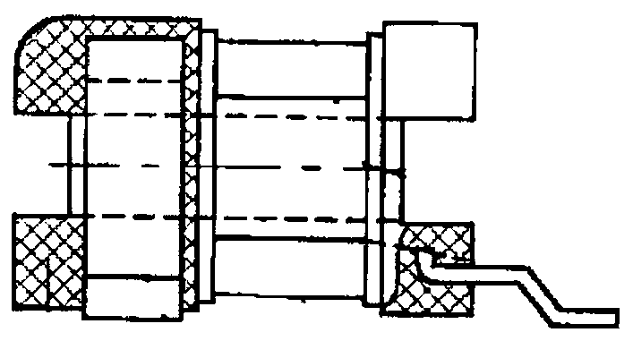
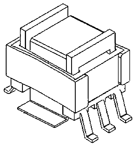
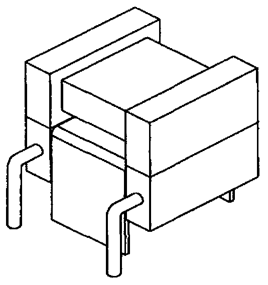

Image

  • Current transformer and manufacturing method thereof
  • Current transformer and manufacturing method thereof
  • Current transformer and manufacturing method thereof

Examples


Embodiment Construction

[0087] The cause of the present invention, terms used, and inventive concept are briefly described first.

[0088] Currently commonly used current transformers, no matter whether they use the skeleton or the magnetic core as the carrier of the secondary multi-winding, or the primary metal guide piece embedded or added, are inseparable from the enameled wire winding process.

[0089] PCB (Printed Circuit Board) printed board refers to a circuit board (hereinafter referred to as PCB board) that is used in electronic and electrical products to carry out copper-clad wiring on an insulating medium to realize electrical connections between electronic devices. Since IBM took the lead in developing high-density multilayer boards (SLC) in 1991, some well-known large companies in the industry have also successively developed various high-density interconnection (HDI) microporous boards. The rapid progress of these processing technologies has prompted the design of PCBs to gradually deve...


PUM


Abstract

The invention provides a current transformer and a manufacturing method thereof. The current transformer is formed by assembling an upper magnetic core, a multi-layer PCB and a lower magnetic core, wherein the upper magnetic core comprises a magnetic core upper panel, a middle column located in the center of the upper panel and two side columns which are in the same direction as the middle column,are parallel to the middle column, are arranged in a mirroring mode and are flush with an edge of the magnetic core upper panel, the lower magnetic core comprises a magnetic core bottom column, a middle column located in the middle of the magnetic core bottom column and two side columns which are parallel to the middle column in the same direction and are symmetrically arranged, the middle columnof the upper magnetic core and the middle column of the lower magnetic core are equal in sectional area and equal in width and section, and the magnetic core panel of the upper magnetic core and themagnetic core bottom column of the lower magnetic core are equal in thickness. The current transformer is advantaged in that only combination of the magnetic core and the multi-layer PCB is provided,and process difficulty is low.

Description

technical field [0001] The invention relates to the technical field of low-voltage electrical appliances, in particular to a structure of a current transformer used in a low-power high-frequency switching power supply and an assembly and manufacturing method thereof. Background technique [0002] The current transformer is a special magnetic device commonly used in switching power supplies. It is widely used to track and detect the current in the circuit by connecting with the switching device. Its design principle is also different from conventional electronic transformers. The primary is generally one turn or a few turns, and the number of secondary turns is many. The turns ratio between the primary and secondary is generally 1:50 or more. (Reference book number ISBN: 9787538136043, the ninth chapter of "Magnetic Components Part Volume of Practical Power Supply Technology Handbook" published by Liaoning Science and Technology Press in 2002). [0003] As a current transfor...

Claims


Application Information

Patent Timeline
Patent Type & Authority Applications(China)
IPC IPC(8): H01F27/24H01F27/28H01F27/29H01F27/30H01F27/34H01F27/36H01F38/30H01F41/00
CPCH01F27/24H01F27/2804H01F27/292H01F27/303H01F27/346H01F27/36H01F38/30H01F41/00H01F2027/2809
Inventor 向宇峰刘伟周洪滔
Owner MORNSUN GUANGZHOU SCI & TECH
Learn More