Supercharge Your Innovation With Domain-Expert AI Agents!

Geostationary orbit high-resolution monitoring imaging satellite system and method

A high-resolution, imaging satellite technology, applied in the field of optical remote sensing satellites, can solve the problems of small field of view/width, ten minutes or even hours, large data volume, etc., to achieve the effect of shortening the lag time

Active Publication Date: 2020-05-01
CHINA ACADEMY OF SPACE TECHNOLOGY
View PDF11 Cites 4 Cited by
  • Summary
  • Abstract
  • Description
  • Claims
  • Application Information

AI Technical Summary

Problems solved by technology

Due to the need for a high signal-to-noise ratio, there are very stringent requirements for detectors and imaging circuits, coupled with the large amount of data, the data processing on the star is also facing major challenges
In addition, fast and reliable identification of moving targets and high-precision vector indication are required. The redundancy of background data is too large, and high-efficiency near-real-time processing is very difficult.
[0005] In order to achieve high-resolution optical surveillance imaging in geostationary orbits, cameras generally use a reflective optical system with a single field of view. Large field of view, taking into account the difficulty and cost of developing high resolution and large field of view
Usually, the open-loop high-resolution satellite system needs to be guided by other systems to complete passive search and discovery in a large area, and then the high-resolution imaging system can perform tracking and monitoring tasks in local areas, which has a long existence. Time lag effect (usually on the order of tens of minutes or even hours), it is difficult for a single satellite to achieve fast and precise feedback pointing control, and it is difficult to achieve closed-loop long-term continuous tracking and monitoring of moving targets

Method used


Image

  • Geostationary orbit high-resolution monitoring imaging satellite system and method
  • Geostationary orbit high-resolution monitoring imaging satellite system and method
  • Geostationary orbit high-resolution monitoring imaging satellite system and method

Examples


Embodiment

[0063] In the following, the feasibility and applicability of the surveillance imaging system of the present invention will be described through the design embodiment of the 1m / 20m dual-resolution / dual-field-of-view satellite system.

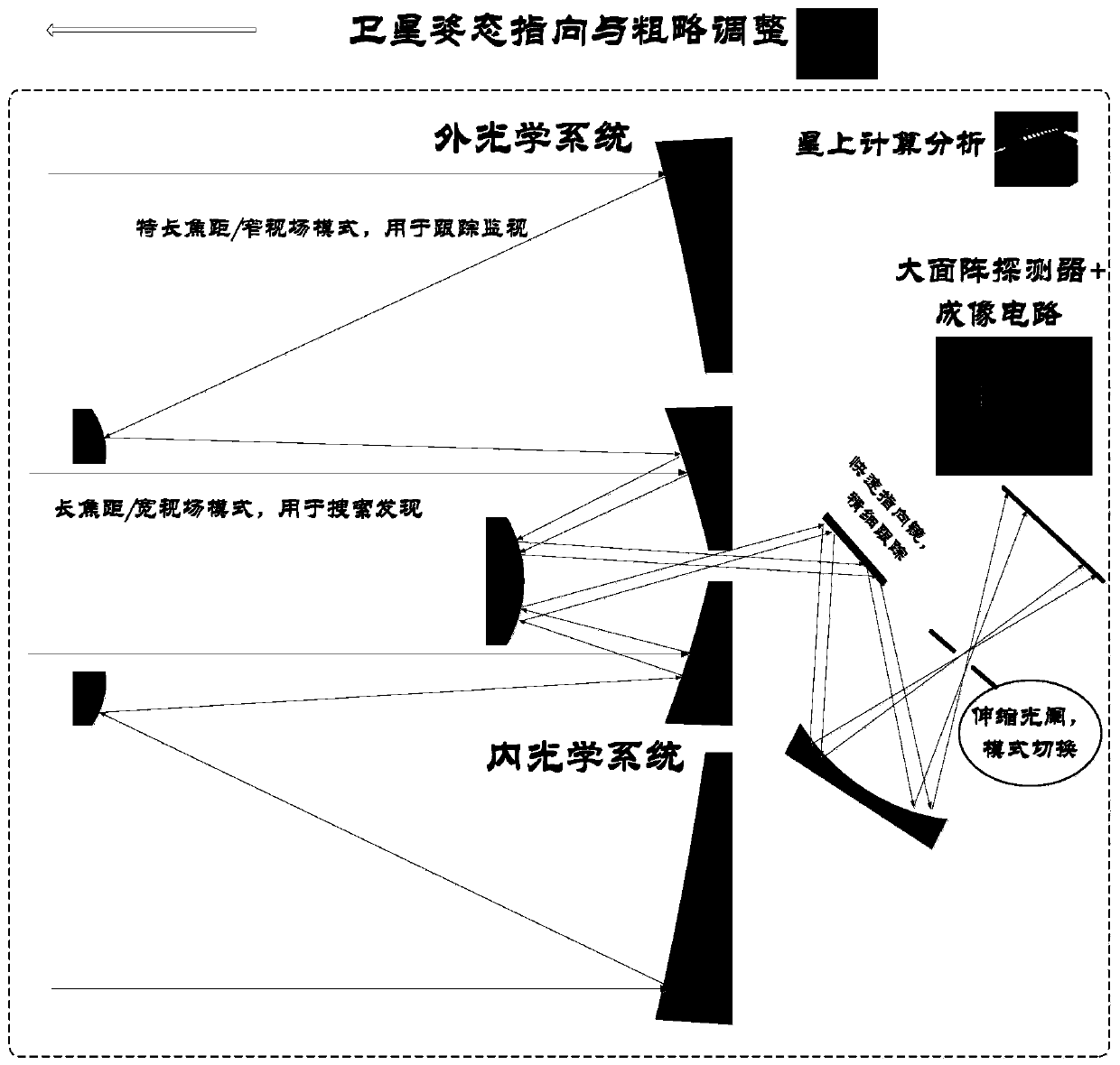
[0064] 1. Internal optical subsystem

[0065] The internal optical subsystem realizes a large field of view with a long focal length. The TMA triple-mirror coaxial optical system with a relatively small aperture (primary mirror is about Φ=1.5m) has a focal length of about 10m (corresponding to a camera resolution of about 20m). The angle is about 1.6°*1.6° (the corresponding camera ground width is about 1000km*1000km).

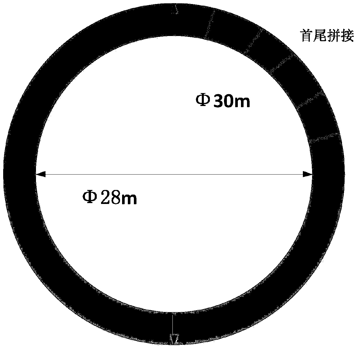
[0066] 2. External optical subsystem

[0067] The external optical subsystem realizes a small field of view with a very long focal length, and a large-caliber (outer diameter of the primary mirror is about Φ=30m, and an inner diameter of about Φ=28m) primary and secondary mirror coaxial annular optical system, which can be comp...


PUM


Abstract

According to the geostationary orbit high-resolution monitoring imaging satellite system and method, a large-obscuration annular reflection optical system is adopted, high resolution is achieved withrelatively low cost and high maturity, the defects of a single-field-of-view fixed-focus imaging system are overcome, and the bottleneck problem that high resolution and a large field of view are difficult to consider at the same time is solved. The system has the capabilities of large-range high-resolution active search discovery and small-range very-high-resolution long-time continuous trackingand monitoring, and in-orbit closed-loop monitoring imaging is realized. Rapid switching of two modes is achieved through a telescopic diaphragm in the camera, and the unique function of active searchdiscovery, namely continuous tracking and monitoring, is achieved under the cooperation of satellite attitude rough pointing adjustment and camera internal fine pointing adjustment.

Description

technical field [0001] The invention relates to a geostationary orbit high-resolution monitoring and imaging satellite system and method, which belong to the technical field of optical remote sensing satellites, and are especially suitable for optimal design and engineering realization of geostationary orbit high-resolution satellites. Background technique [0002] Geostationary orbit satellites are well suited for long-duration continuous surveillance imaging. However, compared with the low-orbit satellites of about 500km, taking the geostationary orbit altitude of about 36,000km as an example, the imaging object distance is more than 72 times higher. There are many challenges in the optical imaging satellite system, mainly in: (1) the development of long-focus and large-aperture optical systems brought about by high spatial resolution is difficult; The splicing and output of the area array requires a large amount of data; (3) It is difficult to balance high resolution and...

Claims


Application Information

Patent Timeline
Patent Type & Authority Applications(China)
IPC IPC(8): H04N5/225H04N5/232H04N7/20
CPCH04N7/20H04N23/55H04N23/67H04N23/667H04N23/695
Inventor 满益云
Owner CHINA ACADEMY OF SPACE TECHNOLOGY
Features
  • R&D
  • Intellectual Property
  • Life Sciences
  • Materials
  • Tech Scout
  • Unparalleled Data Quality
  • Higher Quality Content
  • 60% Fewer Hallucinations
Learn More