Adjusting device with a sealed guide cylinder

A technology for regulating devices and guiding sleeves, which is applied in the direction of valve devices, electromagnets with armatures, electromagnets, etc., which can solve problems such as lubricant escape, weakened sealing effect of seals, and jamming, and achieve large manufacturing tolerances Effect

Inactive Publication Date: 2020-05-01
KENDRION VILLINGEN GMBH
View PDF13 Cites 2 Cited by
  • Summary
  • Abstract
  • Description
  • Claims
  • Application Information

AI Technical Summary

Problems solved by technology

It has been shown that, on the one hand, the tension causes the tappet to tilt or jam in the guide sleeve, and on

Method used


Image

  • Adjusting device with a sealed guide cylinder
  • Adjusting device with a sealed guide cylinder

Examples


Embodiment Construction

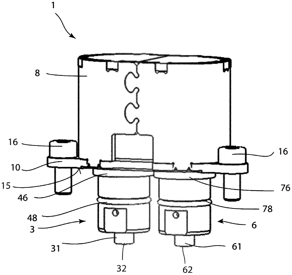
[0029] Refer below figure 1 and figure 2The adjusting device 1 according to a preferred embodiment of the present invention is described in detail.

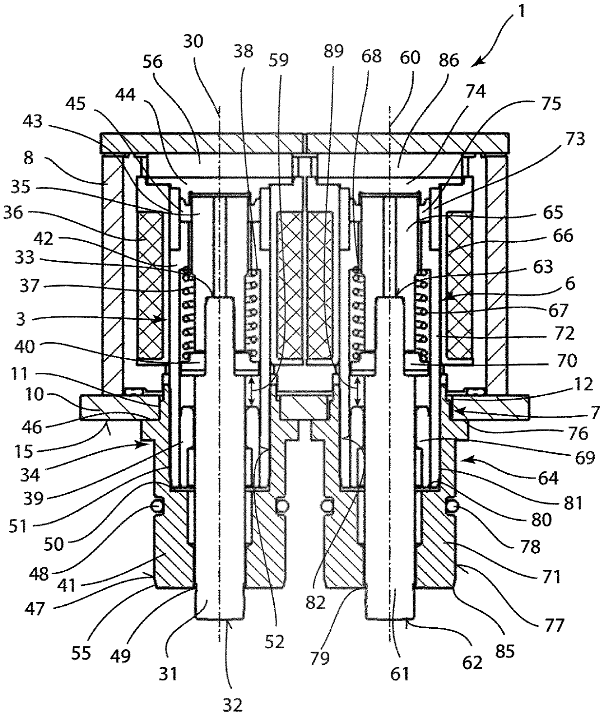
[0030] figure 1 The adjusting device 1 is shown with a first tappet assembly 3 , a second tappet assembly 6 and a connecting plate 10 . A web 10 is provided for fixing the adjusting device 1 to a not shown camshaft housing. The lifter assemblies 3, 6 are substantially identical in structure and are parallel to and spaced apart from each other, and each lifter assembly 3, 6 comprises a lifter 31, 61 which moves longitudinally along the longitudinal axis 30, 60 The working strokes 59 , 89 are arranged in the respective guide cylinder 34 , 64 . exist figure 2 The working strokes 59 , 89 are shown by double arrows.

[0031] The respective tappet 31 , 61 has a front end 32 , 62 and a rear end 33 , 63 , the front end 32 , 62 protruding through a pilot cylinder opening 59 , 79 machined into the respective pilot cylinder 34 , 64 ...


PUM


Abstract

The invention relates to an adjusting device (1) having at least one tappet assembly (3, 6). The at least one tappet assembly (3, 6) comprises a tappet (31, 61), at least one guide cylinder (34, 64),and a pole core (44, 74). The tappet (31, 61) is arranged in the guide cylinder (34, 64) in a movable manner along a longitudinal axis (30, 60), and a non-magnetic connection socket (43, 73) is arranged between the guide cylinder (34, 64) and the pole core (44, 74). The guide cylinder (34, 64) and the pole core (44, 74) are arranged at a distance to each other in the longitudinal axis (30, 60) bymeans of the connection socket (43, 73).

Description

technical field [0001] The invention relates to an adjusting device according to the preamble of claim 1 and to a motor vehicle having such an adjusting device. The invention relates in particular to a control device for varying the valve opening and / or valve opening time in an internal combustion engine and / or to a control device for deactivating partial cylinders of an internal combustion engine. Background technique [0002] Regulating devices, in particular with electromagnetically operated actuators, are used in motor vehicle technology for opening and closing intake and exhaust valves of diesel and / or gasoline engine cylinders, which will A fuel mixture is introduced into the combustion chamber and combusted exhaust gases exit the combustion chamber. In order to achieve the highest possible efficiency of the internal combustion engine, the opening and closing times of the valves need to be precisely adjusted, which takes place via the valve control or the valve train....

Claims


Application Information

Patent Timeline
IPC IPC(8): F01L13/00
CPCF01L13/0036F01L2013/0052F01L2013/101F01L2820/031H01F7/081H01F7/1607H01F2007/085H01F2007/1692F01L1/14F01L1/22F01L1/46F01L2820/00H01F7/16
Inventor 楚尼奥·苏祖吉沃尔弗拉姆·麦沃尔德哈拉尔德·伯卡特迈克尔·蒂施斯彻克安德列亚斯·卡默勒
Owner KENDRION VILLINGEN GMBH
Why Eureka
Try Eureka