Power channel structure crossing subway route

A channel structure and line technology, used in tunnels, tunnel linings, underground chambers, etc., can solve problems such as difficulty in ensuring the safety of construction workers, cutting of large-grained pebble strata, and large stratum settlement and deformation, and achieve efficient construction and prevent road surface. The effect of settlement deformation and improving the degree of fragmentation

Pending Publication Date: 2020-05-05
成都建工第二建筑工程有限公司
View PDF0 Cites 0 Cited by
  • Summary
  • Abstract
  • Description
  • Claims
  • Application Information

AI Technical Summary

Problems solved by technology

In the face of such geological conditions, if traditional manual excavation is used for pipe jacking construction, dewatering treatment is required, resulting in large subsidence and deformation of the ground, making it difficult to ensure the safety of construction personnel. Pipe jacking construction is difficult to han

Method used


Image

  • Power channel structure crossing subway route
  • Power channel structure crossing subway route
  • Power channel structure crossing subway route

Examples


Embodiment 1

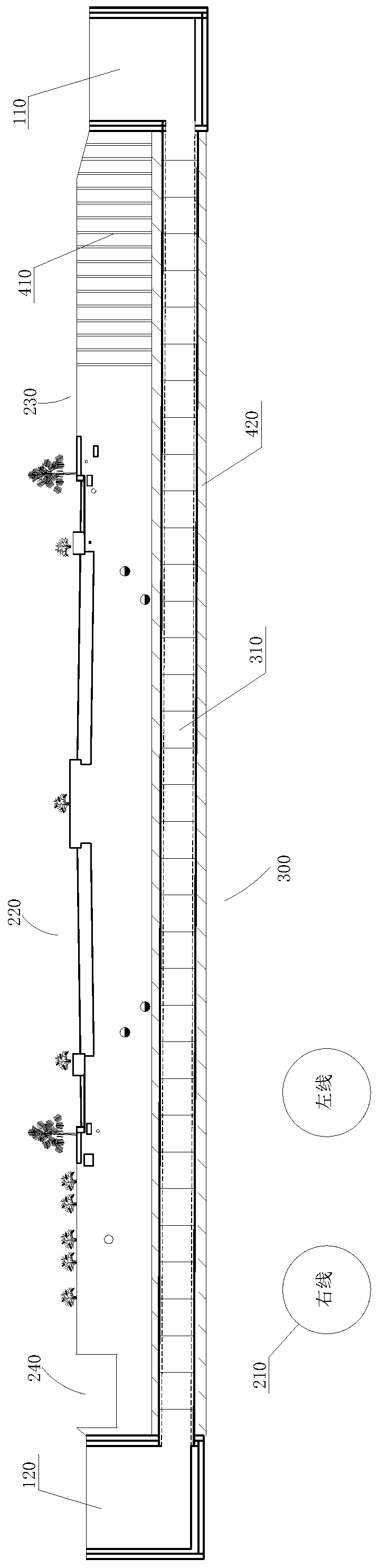
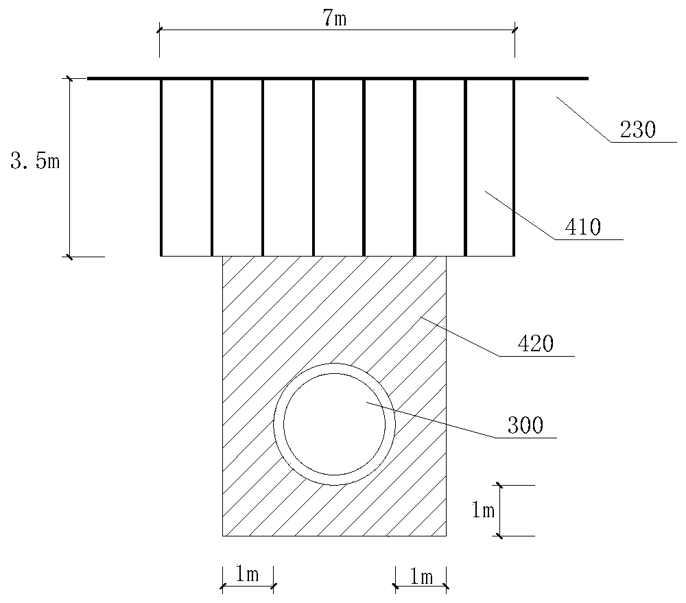
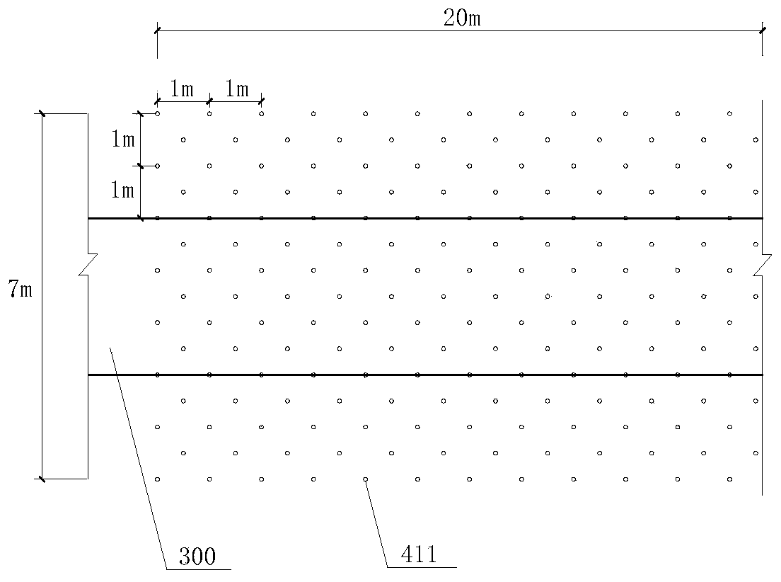
[0062] Such as figure 1 The power channel structure across the subway line shown includes the originating shaft 110, the receiving shaft 120, the pipe jacking section 300 connecting the originating shaft 110 and the receiving shaft 120, and the reinforcement structure, and the pipe jacking section 300 includes concrete pipes connected end to end Section 310.

[0063] The originating shaft 110 and the receiving shaft 120 are respectively located on both sides of the existing subway line 210, and the distance between the originating shaft 110 and the existing subway line 210 is greater than the distance between the receiving shaft 120 and the existing subway line 210; The road between the receiving shaft 120 and the originating shaft 110 includes the existing road 220 and the undisturbed soil 230 on both sides of the existing road 220; the cross section of the originating shaft 110 is a rectangle; the cross section of the receiving shaft 120 is a circle shape.

[0064] The bur...

Embodiment 2

[0070] Such as Figure 5-7 The mud-water balance shield machine shown includes a rotatable cutter head 500, a cutting mechanism, a twisting leg 540, a disc body 800, a first grouting mechanism, a second grouting mechanism and a third grouting mechanism, the disc body 800 and the third grouting mechanism A crushing bin 550 is formed between the cutter heads 500, and a muddy water bin 830 is formed behind the disc body 800.

[0071] Such as Figure 5 As shown, the cutterhead 500 has a tapered surface 510 with a gradually decreasing cross-section and a propulsion surface 520 matched with the palm surface. The propulsion surface 520 is provided with a feed port 530, and the opening ratio of the cutterhead 500 is 29%. There are four feed ports 530 and they are distributed symmetrically with the center of the propulsion surface 520; the feed ports 530 extend to the end of the conical surface 510; gradually increase;

[0072] The cutting mechanism includes a first cutting assembly...


PUM

PropertyMeasurementUnit
Depthaaaaaaaaaa
Widthaaaaaaaaaa

Abstract

The invention discloses a power channel structure crossing a subway route. The power channel structure comprises an originating well, a receiving well and a jacking pipe segment connecting the originating well with the receiving well. The originating well and the receiving well are located on the two sides of an existing subway route, the distance between the originating well and the existing subway route is larger than that between the receiving well and the existing subway route, a pipeline between the receiving well and the originating well comprises an existing highway and original soil onthe two sides of the existing highway, the jacking pipe segment is located between the road surface and the existing subway route, a reinforcing structure is further included, and comprises a first reinforcing structure at least arranged in the original soil between the originating well and the existing highway and a second reinforcing structure located outside a concrete pipe segment, the reinforcing structure is arranged in the original soil, on the premise of ensuring the reinforcing effect, the influence on the operation of the existing highway can be avoided, partition reinforcing in theheight direction is carried out, and the construction time is shortened on the premise of ensuring the reinforcing effect.

Description

technical field [0001] The invention relates to the technical field of underground excavation pipeline construction, in particular to a power channel structure spanning a subway line. Background technique [0002] The construction of power tunnels usually adopts the open and cut method to improve construction efficiency. However, for the construction of power tunnels that need to cross special road sections such as existing highways with heavy traffic volume, the open and cut method is not applicable. For road sections where the open cut method is not applicable, a new construction method, pipe jacking construction, has been developed. Pipe jacking construction belongs to the non-excavation construction method, which is a pipeline burying construction technology with no excavation or less excavation. The pipe jacking method uses the jacking force to overcome the friction between the tunneling equipment pipeline and the surrounding soil, so that the tunneling equipment (suc...

Claims


Application Information

Patent Timeline
IPC IPC(8): E21D9/06E21D9/08E21D9/12E21D11/10E21D11/38
CPCE21D9/0607E21D9/0635E21D9/08E21D9/12E21D11/105E21D11/38
Inventor 薛庆文刘刚林裕尹超田泽辉傅宇张宇赵振蜀
Owner 成都建工第二建筑工程有限公司
Why Eureka
Try Eureka