Bearing mounting structure and heat-conducting grease filling method

A technology of installation structure and thermal grease, which is applied to parts of pumping devices for elastic fluids, non-variable pumps, pump components, etc., can solve problems such as poor heat dissipation performance, and achieve extended operating life and axial load bearing Uniform and prevent overheating and burning effect

Pending Publication Date: 2020-05-05
KYKY TECH
View PDF16 Cites 2 Cited by
  • Summary
  • Abstract
  • Description
  • Claims
  • Application Information

AI Technical Summary

Problems solved by technology

[0006] Therefore, the present invention provides a bearing installation structure, a molecular pump and a thermal grea

Method used


Image

  • Bearing mounting structure and heat-conducting grease filling method
  • Bearing mounting structure and heat-conducting grease filling method
  • Bearing mounting structure and heat-conducting grease filling method

Examples


Embodiment 1

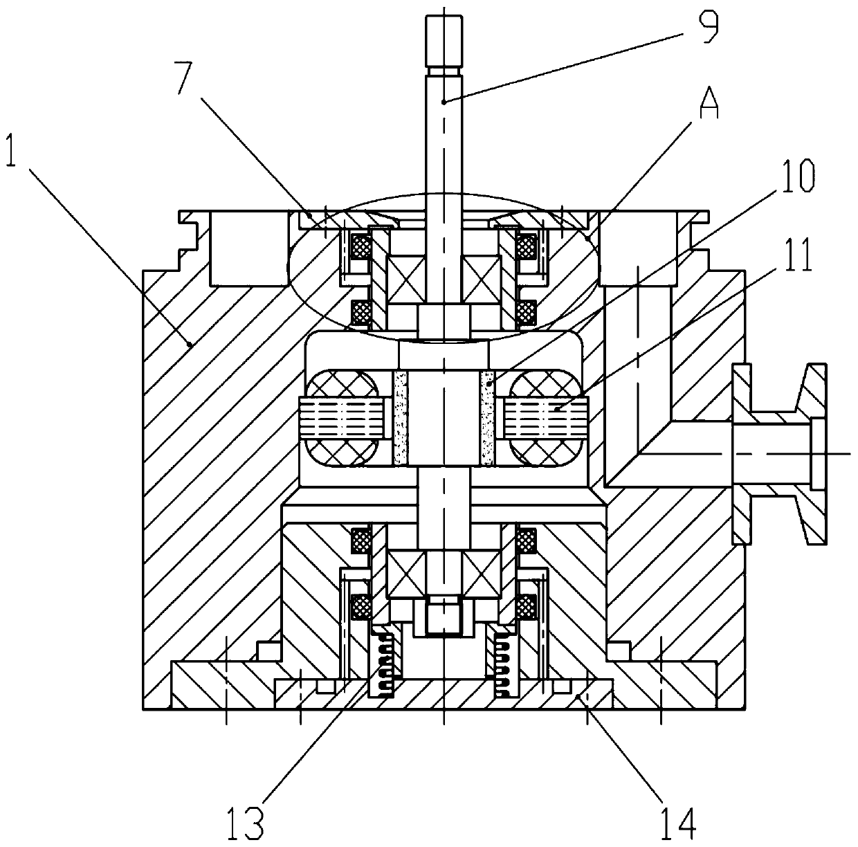
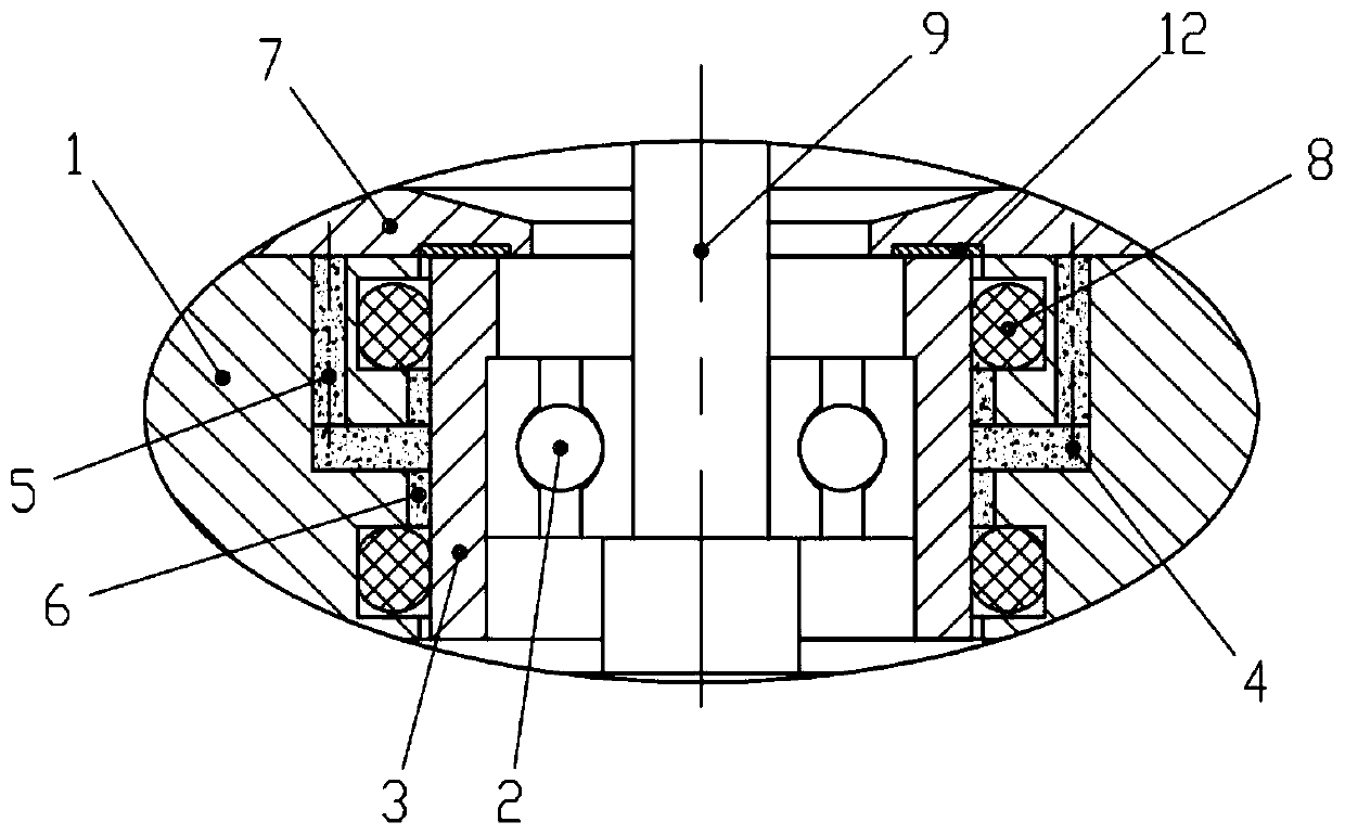
[0033] The following combination figure 1 and figure 2 , an embodiment of the present invention is described:

[0034] Bearings at both ends of the main shaft 9 of the small molecular pump generally adopt the same type, so the same cooling structure can be used. After the bearing bushing 3 and the bearing 2 are assembled, they are installed on both ends of the main shaft 9 respectively, and the main shaft is installed in the bearing seat 1 with the vibration-damping O-ring 8 . An annular cavity 6 is formed between the bearing seat 1, the bearing bush 3, and the double-layer damping O-ring 8, and the outside of the annular cavity 6 communicates with the annular grease groove 4 provided on the bearing seat 1, and the outside of the grease groove 4 The end is provided with a grease injection hole 5 communicating with it. Two grease injection holes 5 are opened symmetrically along the axis of the bearing housing 1 . Use a syringe to fill the grease injection hole 5 at one end ...

Embodiment 2

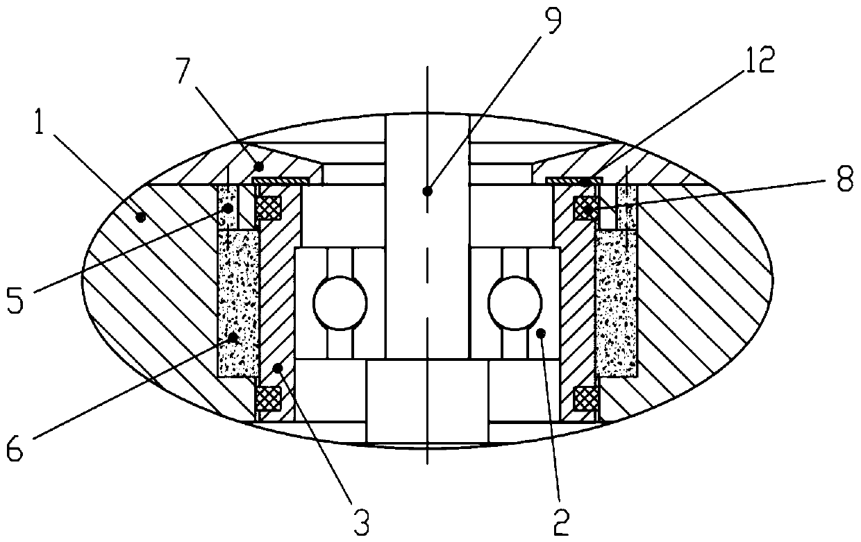
[0040] As an alternative implementation, such as image 3 As shown, when the molecular pump uses a smaller bearing (inner hole 6mm or less), due to the use of double-layer O-rings for vibration reduction, the cross-sectional area of ​​the vibration-damping O-ring 8 can be smaller, for example image 3 The O-ring with a rectangular cross-section is shown, and the supporting structure of the O-ring can be set on the bearing bush 3. The outer wall of the annular cavity 6 on the bearing seat 1 can be extended outward appropriately, and the annular cavity 6 can be directly connected to the grease injection hole 5 (that is, without The grease injection groove described in Embodiment 1) is connected, so that the grease injection path can be shortened, and the grease injection resistance is smaller, so as to ensure that the thermal conductive grease fills the annular cavity 6 .

[0041] Using the above-mentioned bearing installation structure, according to the molecular pump shafting ...


PUM


Abstract

The invention relates to the technical field of molecular pumps, in particular to a bearing mounting structure and a heat-conducting grease filling method. The bearing mounting structure comprises a bearing with a bearing bush and a bearing seat, wherein the bearing is supported by an upper damping O ring and a lower damping O ring in the radial direction in a damping mode, an annular cavity is formed between the double layers of damping O rings as well as between the outer wall of the bearing bush and the inner wall of the bearing seat, the annular cavity communicates with grease injection holes through an annular groove, and heat-conducting grease is injected through the grease injection holes to fill the annular cavity. By means of the structure, reliable and efficient heat conduction is formed between the bearing and the bearing seat, the bearing mounting structure can efficiently transfer heat generated by high-speed rotation of the bearing to the bearing seat and dissipate the heat to the outside, the bearing can be prevented from being burnt due to overheating, the service life of the bearing is prolonged, and the heat-conducting grease filling method has the advantage of facilitating naked eye observation, and can ensure that the annular cavity is filled with the heat-conducting grease.

Description

technical field [0001] The invention relates to the technical field of molecular pumps, in particular to a bearing installation structure and a method for filling heat-conducting grease. Background technique [0002] Molecular pump is a kind of high-speed rotating mechanical equipment, which uses the collision between multi-stage high-speed rotating blades and gas molecules to exert directional kinetic energy on gas molecules, so that gas molecules are compressed and pumped. There are two lubrication methods for mechanical bearing molecular pumps. Large-scale mechanical bearing molecular pumps use oil lubricated bearings because of their large bearing loads and high heat generation. Small and medium-sized mechanical bearing molecular pumps have small loads. In order to facilitate installation at any angle in the application, the bearings are mostly greased. lubricating. [0003] In order to maintain its pumping performance, small molecular pumps usually rotate at 40,000 rpm...

Claims


Application Information

Patent Timeline
IPC IPC(8): F04D29/056F04D29/58F04D29/66F04D29/64
CPCF04D29/056F04D29/5853F04D29/668F04D29/644
Inventor 邹蒙李赏李兵
Owner KYKY TECH
Why Eureka
Try Eureka