Dynamic hip joint prosthesis control system

A control system and hip joint technology, applied in the direction of prosthesis, medical science, etc., can solve the problems of unable to provide power, no control system, etc., to achieve the effect of flexibility

Inactive Publication Date: 2020-05-08
UNIV OF SHANGHAI FOR SCI & TECH
View PDF12 Cites 2 Cited by
  • Summary
  • Abstract
  • Description
  • Claims
  • Application Information

AI Technical Summary

Problems solved by technology

Traditional hip joint prostheses are mostly bionic hydraulic damping systems, which cannot provide power and do not have a control system

Method used


Image

  • Dynamic hip joint prosthesis control system
  • Dynamic hip joint prosthesis control system
  • Dynamic hip joint prosthesis control system

Examples


Embodiment Construction

[0020] In order to make the technical means, creative features, goals and effects achieved by the present invention easy to understand, the present invention will be described in detail below in conjunction with the embodiments and accompanying drawings.

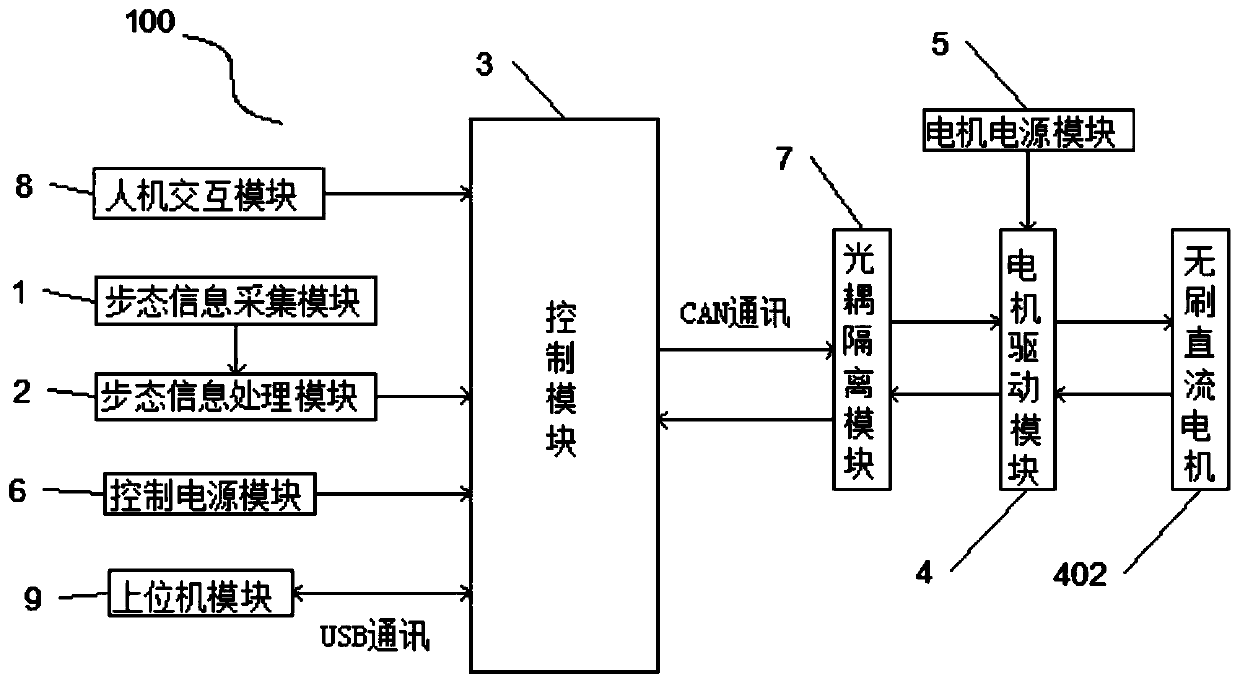
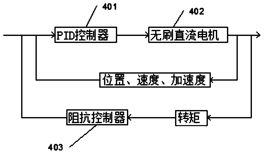
[0021] figure 1 It is a schematic diagram of the control system of the powered hip joint prosthesis in the embodiment of the present invention.

[0022] Such as figure 1 As shown, the present invention provides a powered hip joint prosthesis control system 100, which is used to control a powered hip joint prosthesis with a host computer to help high amputee patients walk, including: gait information acquisition module 1, gait information processing Module 2, control module 3, motor drive module 4, communication module (not shown in the figure), motor power supply module 5, control power supply module 6, optocoupler isolation module 7, Kalman filter module (not shown in the figure), man-machine Interactive module 8 and host...


PUM


Abstract

The invention relates to the field of rehabilitative prosthetics and orthotics, in particular to a dynamic hip joint prosthesis control system. The dynamic hip joint prosthesis control system comprises a gait information collection module, a gait information processing module, a control module, a motor driving module, a communication module, a motor power supply module, a control power supply module, a photo coupler isolation module and a Kalman filtering module; and the control system receives plantar pressure information and knee joint and hip joint flexion and extension information, collected by the gait information collection module, through the communication module, the received information is processed to generate a control signal, and the motor driving device (module) receives the control signal through the communication module to drive a dynamic hip joint prosthesis to run, so as to drive a patient to walk. The provided dynamic hip joint prosthesis control system has the advantage that strength needed by the patient to walk is reduced so that the patient can walk conveniently.

Description

technical field [0001] The invention relates to the field of rehabilitation prosthesis orthopedics, in particular to a dynamic hip joint prosthesis control system. Background technique [0002] Because of some tumors, trauma, pressure sores and vascular diseases, many patients need hip disarticulation surgery. The number of hip dislocations belongs to high amputation, and this type of operation has a great impact on the life and psychology of the amputee. Wearing hip prostheses can greatly compensate for this effect. Traditional unpowered hip joints include the "Artificial Lower Limb Hip Joint" applied by Ottobock Industry Co., Ltd. in 2001 and the utility model patent applied by Henan Prosthetic Center in 2002. "A hip disarticulated joint for prosthetics". Traditional hip joint prostheses are mostly bionic hydraulic damping systems, which do not provide power and do not have a control system. Traditional hip joints require patients to expend nearly twice as much energy a...

Claims


Application Information

Patent Timeline
Patent Type & Authority Applications(China)
IPC IPC(8): A61F2/70
CPCA61F2/68A61F2002/704
Inventor 邓志鹏喻洪流李新伟肖艺璇段崇群吴亮孟利国
Owner UNIV OF SHANGHAI FOR SCI & TECH
Why Eureka
Try Eureka