Additional material rotating worktable with circular cooling function

A rotating table and circulating cooling technology, which is applied in the direction of additive processing, energy efficiency improvement, process efficiency improvement, etc., can solve the problems of low cooling efficiency, difficulty in continuous supply of cooling water, and affecting manufacturing efficiency, so as to improve cooling Efficiency, the effect of guaranteeing process performance

Pending Publication Date: 2020-05-08
佛山宇仁智能科技有限公司
View PDF0 Cites 3 Cited by
  • Summary
  • Abstract
  • Description
  • Claims
  • Application Information

AI Technical Summary

Problems solved by technology

[0003] In this process of additive manufacturing, high heat input is likely to cause rapid heating of the workpiece. In order to ensure product quality, the workpiece needs to be kept in a relatively stable temperature range. The existing production process mainly uses the method of stopping and waiting for natural cooling , this method has low cooling efficiency and affects manufacturing effi

Method used


Image

  • Additional material rotating worktable with circular cooling function
  • Additional material rotating worktable with circular cooling function
  • Additional material rotating worktable with circular cooling function

Examples


Embodiment 1

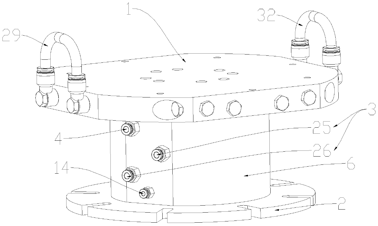
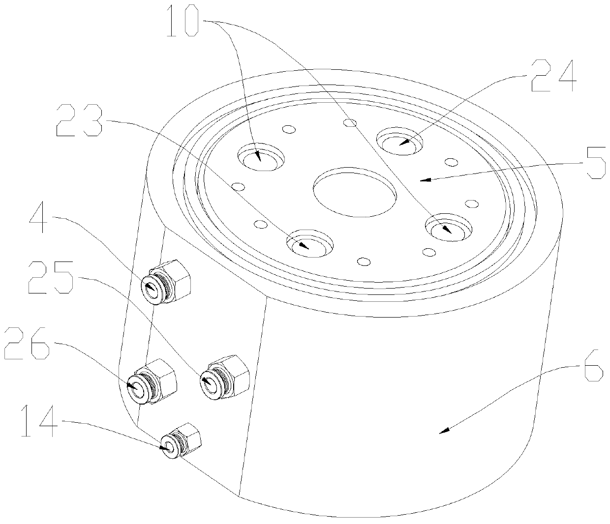
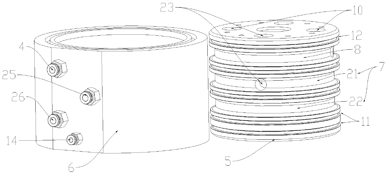
[0034] see Figure 1 to Figure 9 , an additive rotary table 1 with a circulating cooling function, including a rotary table 1, a rotary sealing shaft, and a base 2 connected to an external rotary drive device, wherein the external rotary drive device is generally a drive motor of an additive device or The power output mechanism controlled by the driving motor, such as a reduction box, etc., the top of the rotary sealing shaft is connected to the rotary table 1, the bottom of the rotary sealing shaft is connected to the base 2, and the rotary table 1 is provided with a cooling circuit for the flow of coolant, wherein the cooling circuit For the circulation channel opened by the deep hole processing technology, the cooling liquid inlet 3 and the cooling liquid outlet 4 are arranged on the rotating sealing shaft. The cooling liquid inlet 3 is connected to the cooling liquid outlet 4 through the cooling circuit. During the additive printing process, the workpiece The heat will be ...

Embodiment 2

[0046] This embodiment is the same as embodiment 1 except the following content: see Figure 10 , also includes a wall-attached cooling device, the wall-attached cooling device includes a liquid inlet pipe 33, a liquid outlet pipe 34, a thin steel strip 35, and several heat-dissipating copper blocks 36 that are close to the outer wall of the workpiece 41, and some heat-dissipating copper blocks 36 are fixed by screws Mounted on thin steel strip 35, see Figure 11 and Figure 12 , the heat dissipation copper block 36 has a cooling channel 37 for the circulation of cooling liquid, one end of the liquid inlet pipe 33 is connected to the inlet of the cooling channel 37, and the other end of the liquid inlet pipe 33 is connected to the first serial connection inlet 27 or the second serial connection inlet 30, and the outlet One end of the liquid pipe 34 is connected to the outlet of the cooling passage 37, and the other end of the liquid outlet pipe 34 is connected to the first se...


PUM


Abstract

The invention provides an additional material rotating worktable with a circular cooling function. The worktable comprises a rotating worktable body, a rotating seal shaft and a base connected with anouter rotating driving device, the top of the rotating seal shaft is connected with the rotating worktable body, the bottom of the rotating seal shaft is connected with the base, a cooling loop allowing cooling liquid to flow is arranged on the rotating worktable, a cooling liquid inlet and a cooling liquid outlet are formed in the rotating seal shaft, the cooling liquid inlet communicates with the cooling liquid outlet through the cooling loop, the cooling liquid enters the cooling loop through the cooling liquid inlet, and carries out heat exchange with the rotating worktable body, the temperature of the rotating worktable body is reduced, non-contact workpiece cooling is achieved, and due to a shaft core and a shaft sleeve which can be mutually sealed and rotated, and an annular liquidinlet groove and an annular liquid outlet groove which surround the outer wall of the shaft core, the aim of stably inputting or outputting the cooling liquid to the cooling loop can be achieved.

Description

technical field [0001] The invention relates to the technical field of additive manufacturing equipment, in particular to an additive rotary workbench with a circulating cooling function. Background technique [0002] When performing non-melting extremely inert gas shielded arc additive printing, the control system of the additive equipment controls the welding wire to continuously feed into the arc welding torch head, and the high-temperature arc between the arc welding torch head and the rotary table makes the welding wire melt on the rotary table. Print the bottom plate to form an additive printing layer, and form the workpiece after printing layer by layer. [0003] In this process of additive manufacturing, high heat input is likely to cause rapid heating of the workpiece. In order to ensure product quality, the workpiece needs to be kept in a relatively stable temperature range. The existing production process mainly uses the method of stopping and waiting for natural ...

Claims


Application Information

Patent Timeline
IPC IPC(8): B22F3/105B33Y30/00
CPCB33Y30/00B22F10/10B22F10/00B22F12/37B22F12/20B22F10/20Y02P10/25
Inventor 钟俊超
Owner 佛山宇仁智能科技有限公司
Why Eureka
Try Eureka