A lathe chuck

A technology of lathe chuck and chuck body, which is applied in the field of machine tools, can solve the problems of unfavorable machine tool processing automation, high labor intensity of operators, and large clamping stroke, so as to facilitate automatic clamping, large clamping stroke, and improve production. efficiency effect

Active Publication Date: 2021-08-03
洛阳先驱自动化设备有限公司
View PDF8 Cites 0 Cited by
  • Summary
  • Abstract
  • Description
  • Claims
  • Application Information

AI Technical Summary

Problems solved by technology

The flat spiral disc mechanical chuck or the screw type four-jaw mechanical chuck has a large clamping stroke, which is suitable for processing workpieces with large diameter differences. Facilitate the automation of machine tool processing

Method used


Image

  • A lathe chuck
  • A lathe chuck
  • A lathe chuck

Examples


Embodiment 1

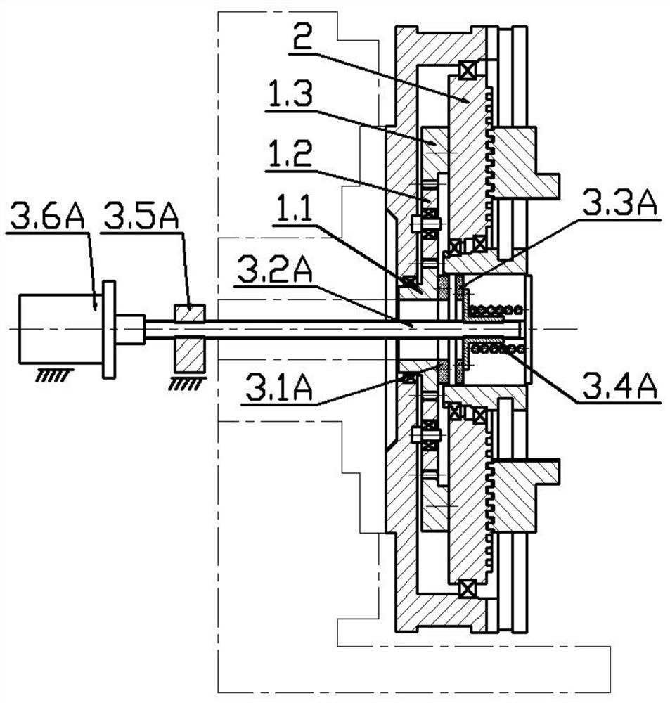
[0035] Such as figure 1 A horizontal lathe chuck shown is coaxially provided with a planetary reduction mechanism 1 in the chuck body, the output end of the planetary reduction mechanism 1 is connected to the spiral groove disk 2 in the chuck body, and the input end is movably connected with resistance Torque input mechanism. In order to increase the output torque at the output end of the planetary reduction mechanism 1, the output end of the planetary reduction mechanism 1 is a low-speed end, and the input end of the planetary reduction mechanism 1 is a high-speed end. The planetary reducer has three deceleration and boosting methods. In this embodiment, the resistance torque input mechanism is connected with the sun gear 1.1 of the planetary reduction mechanism 1, the spiral groove disc 2 is connected with the inner ring gear 1.3 of the planetary reduction mechanism 1, and the planetary The frame 1.2 is fixedly connected with the chuck body. The resistance torque input mec...

Embodiment 2

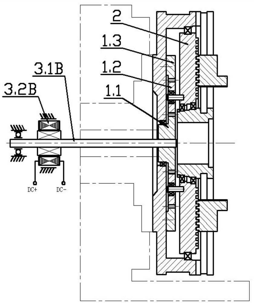
[0039] Such as figure 2 In the shown horizontal lathe chuck, a planetary reduction mechanism 1 is coaxially arranged in the chuck body. The output end of the planetary reduction mechanism 1 is a low-speed end, and the input end of the planetary reduction mechanism 1 is a high-speed end. The low-speed end of the planetary reduction mechanism 1 is connected to the spiral groove disc 2 in the chuck body, and the high-speed end is movably connected with a resistance torque input mechanism. Specifically, the resistance torque input mechanism is connected to the sun gear 1.1 of the planetary reduction mechanism 1, the spiral groove disc 2 is connected to the planet carrier 1.2 of the planetary reduction mechanism 1, and the ring gear 1.3 is fixedly connected to the chuck body. It can be seen that the input resistance torque with high speed and small torque input by the resistance torque input mechanism will also generate an output torque with low speed and high torque at the output...

Embodiment 3

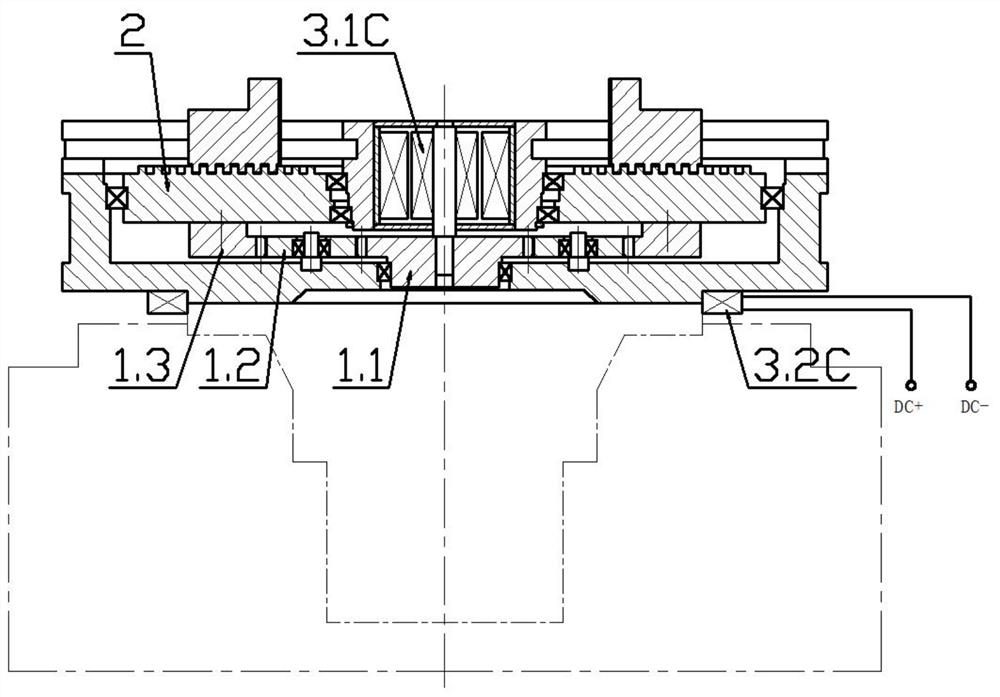
[0043] Such as image 3 As shown in a vertical lathe chuck, the resistance torque input mechanism includes a DC torque motor 3.1C arranged in the shaft center hole of the chuck body, wherein the housing of the DC torque motor 3.1C is connected to the shaft of the chuck body The center hole is connected, the motor shaft of the DC torque motor 3.1C is coaxially connected with the sun gear 1.1, the spiral groove disc 2 is connected with the ring gear 1.3 of the planetary reduction mechanism 1, and the planet carrier 1.2 is fixedly connected with the chuck body. The power input end of the DC torque motor 3.1C is connected with the chuck opening and closing control circuit of the lathe through the conductive slip ring connector 3.2C.

[0044] The chuck body is fixedly connected to the spindle of the lathe. The rotation of the spindle serves as the power source for the chuck to clamp or loosen the workpiece. The spindle of the lathe rotates forward or reverse, and the spiral groove ...


PUM


Abstract

A lathe chuck, comprising a chuck body coaxially provided with a planetary reduction mechanism in the chuck body, the output end of the planetary reduction mechanism is connected to a spiral groove disc in the chuck body, and the input end is movably connected with a resistance torque input mechanism; The spiral grooved disk rotates synchronously with the chuck body. When the input end of the planetary reduction mechanism is connected to the resistance torque input mechanism, the spiral grooved disk rotates relative to the chuck body, so that the multiple jaws connected to the spiral grooved disk move along the chuck simultaneously. Radial movement of the disc body. The invention realizes the free adjustment of the workpiece clamping force through the control of the resistance torque input from the outside, and also realizes the controllability of the opening and closing positions of the jaws by combining with the numerical control system. The invention has large clamping stroke and multiple control functions, reduces labor intensity, improves production efficiency, and facilitates the realization of machine tool processing automation.

Description

technical field [0001] The invention relates to the technical field of machine tools, in particular to a lathe chuck. Background technique [0002] The lathe has a development history of more than 200 years. As the chuck for clamping the workpiece, it is also continuously improved and perfected. The most mature and widely used is the flat spiral disk mechanical chuck, which is realized by rotating the flat spiral disk to drive the jaws to move. Clamping of the workpiece. With the improvement of machine tool processing automation, hydraulic chucks, pneumatic chucks, and electric chucks have appeared one after another. This type of power chuck does not need to manually clamp the workpiece. The outstanding advantages are low labor intensity, high efficiency, and high degree of automation. But there are also great limitations. Hydraulic chucks and pneumatic chucks are mainly reflected in the limited clamping stroke. They are suitable for batch processing of workpieces with simi...

Claims


Application Information

Patent Timeline
Patent Type & Authority Patents(China)
IPC IPC(8): B23B31/163
CPCB23B31/16037
Inventor 吕梦龙
Owner 洛阳先驱自动化设备有限公司
Why Eureka
Try Eureka