Automatic tin surface tracking mechanism of inductor tin soldering machine

An automatic tracking, soldering machine technology, applied in welding equipment, auxiliary devices, metal processing equipment, etc., can solve the problem that the pins of the inductive components are not completely immersed in the tin material, the operator's technical requirements and experience requirements are high, and the operation is increased. Workload and other issues, to reduce labor intensity and technical requirements, improve quality, improve production efficiency

Pending Publication Date: 2020-05-08
揭阳市揭东区新美得福电子有限公司 +1
View PDF0 Cites 2 Cited by
  • Summary
  • Abstract
  • Description
  • Claims
  • Application Information

AI Technical Summary

Problems solved by technology

[0002] The inductance soldering machine is a kind of equipment used for soldering the enameled wire head and pins at the root of the inductance magnetic core during the production process of the inductance. At the same time, the two ends of multiple inductance components are soldered. At present, the original inductance soldering machine is to immerse the inductance components in the tin by moving the manipulator up and down for welding, and the manipulator is driven by two points of the cylinder. The position remains constant, and since both ends of multiple inductance components need to be soldered by dipping tin, the consumption of tin material is relatively fast, and the decline of the tin surface in the tin furnace is also obvious. Therefore, it is necessary for workers to pay frequent attention to the change of the tin surface in the tin furnace and add tin material in time. When the tin surface drops, it is easy for the pins of the inductance element to not be completely submerged in the tin material. Therefore, the operator needs to rework and weld the inductance element detected by the virtual welding, which not only increases the workload of the operator, but also requires higher technical requirements and experience for the operator.

Method used


Image

  • Automatic tin surface tracking mechanism of inductor tin soldering machine
  • Automatic tin surface tracking mechanism of inductor tin soldering machine
  • Automatic tin surface tracking mechanism of inductor tin soldering machine

Examples


Embodiment 1

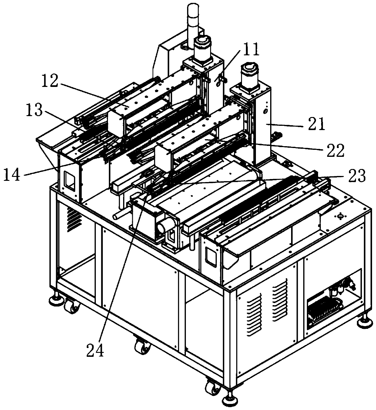
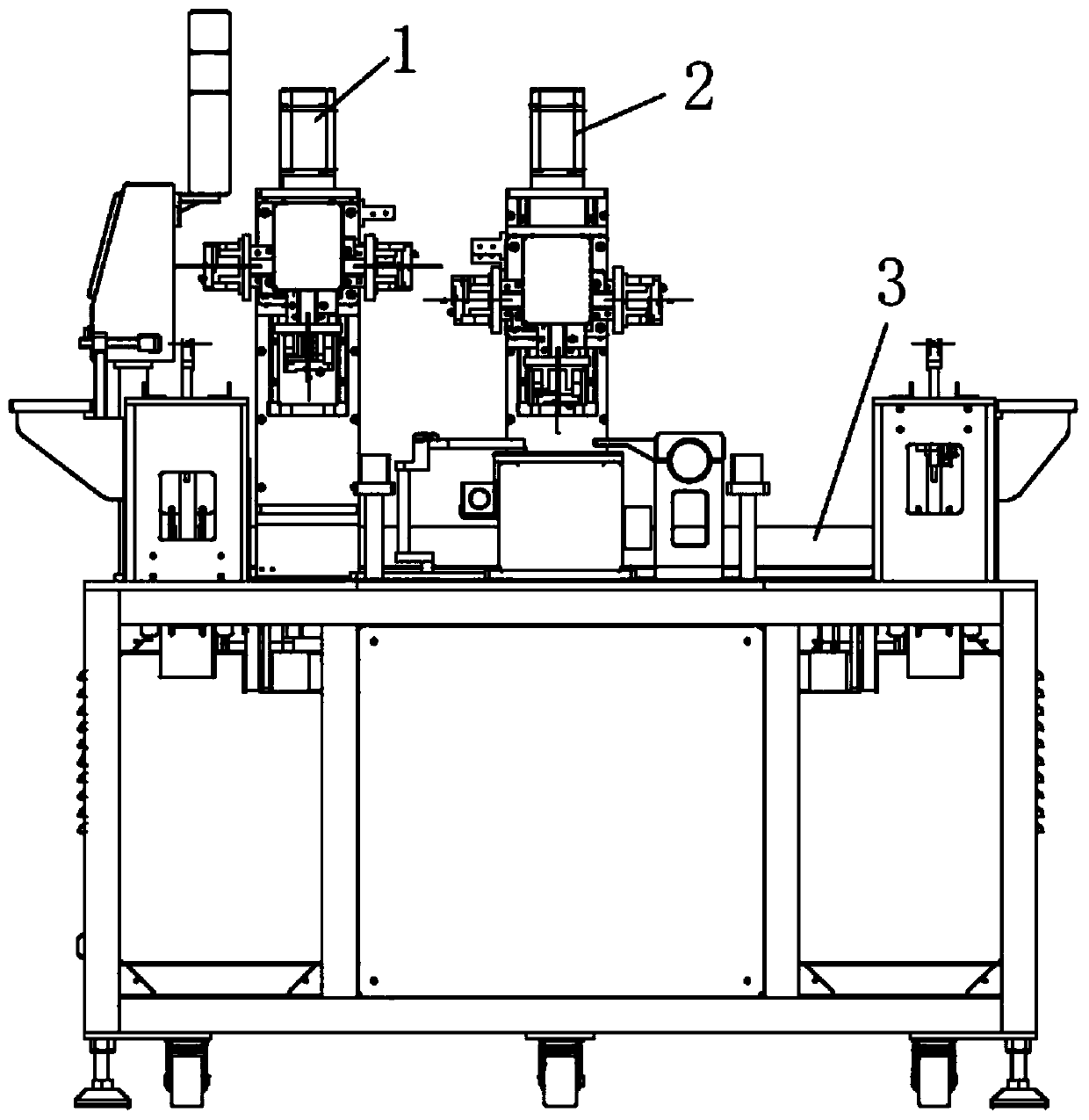
[0019] Example 1: Reference Figure 1-6 , An automatic tracking tin surface mechanism of an induction soldering machine, comprising a horizontal drive mechanism 3 and a first manipulator 1 and a second manipulator 2 arranged on the horizontal drive mechanism 3. The first manipulator 1 includes a first vertical drive connected in turn The mechanism 11, the first rotary drive mechanism 12 and the first clamping mechanism 13, the second manipulator 2 includes a second vertical drive mechanism 21, a second rotary drive mechanism 22, and a second clamping mechanism 23 that are drive-connected in sequence; The drive mechanism 11 and the second vertical drive mechanism 21 both adopt a linear drive structure driven by a servo motor. The end of the first clamping mechanism 12 is fixedly provided with a first tin surface detection component 14, and the end of the second clamping mechanism 22 is fixedly provided with a second Tin surface detection component 24.

[0020] In this embodiment, ...


PUM


Abstract

The invention relates to the technical field of inductor machining equipment, in particular to an automatic tin surface tracking mechanism of an inductor tin soldering machine. According to the technical scheme, the automatic tin surface tracking mechanism of the inductor tin soldering machine comprises a horizontal driving mechanism, a first mechanical arm and a second mechanical arm, wherein vertical driving mechanisms of the first mechanical arm and the second mechanical arm both adopt linear driving structures driven by servo motors; and tin surface detection mechanisms are arranged on clamping mechanisms of the first mechanical arm and the second mechanical arm. The automatic tin surface tracking mechanism of the inductor tin soldering machine has the advantages that a two-point driving mode by air cylinders of existing mechanical arms is changed into a driving mode that the servo motors drive ball screws, so that the mechanical arms for clamping an inductor element are capable ofmoving at any positions and matching with detection electrodes to automatically track the height of a tin surface, thus it is ensured that pins of the inductor element are completely immersed in tinmaterial, the welding quality of the inductor element and the production efficiency are improved, the labor intensity and technical requirements for operators are reduced, and the automatic productionthat the plurality of tin soldering machines are operated by one person is realized.

Description

Technical field [0001] The invention relates to the technical field of inductance processing equipment, in particular to an automatic tracking tin surface mechanism of an inductance soldering machine. Background technique [0002] The induction soldering machine is a kind of equipment used to weld the enameled wire heads and pins at the root of the inductor core during the inductor production process. The equipment adopts immersion tin soldering (that is, all parts other than the entire core are immersed in tin). At the same time, the pins of multiple inductance components are welded at the same time. At present, the original inductance soldering machine uses the up and down movement of the manipulator to immerse the inductance element in the tin for welding, and the manipulator uses the two-point drive method of the cylinder to work. The position is constant, and since both ends of multiple inductance components need to be immersed in soldering, the consumption of tin material i...

Claims


Application Information

Patent Timeline
Patent Type & Authority Applications(China)
IPC IPC(8): B23K1/08B23K3/08
CPCB23K1/08B23K3/08
Inventor 王燕起魏丹玲周靖方政李少波王逸刘如鸿
Owner 揭阳市揭东区新美得福电子有限公司
Why Eureka
Try Eureka