High-voltage direct-current supporting capacitor shell accessory welding tool clamp

A welding jig and high-voltage DC technology, applied in the field of welding jig, can solve the problems of single position limitation, poor position, unable to meet the welding requirements of lifting lug accessories, etc., and achieve the effect of preventing position movement and saving adjustment time.

Inactive Publication Date: 2020-05-08
TONGLING LONGJIA ELECTRICAL
View PDF0 Cites 0 Cited by
  • Summary
  • Abstract
  • Description
  • Claims
  • Application Information

AI Technical Summary

Problems solved by technology

[0005] In order to make up for the deficiencies of the existing technology and solve the problem in the prior art, the position of the lifting lug attachment welded outside the high-voltage DC support capacitor shell is poor, the consistency is low, and the appearance quality is difficult to meet the high requirements of the high-voltage DC support capacitor shell, and the traditional The lifting lug attachment welding fixture has a high degree of unity, and the position is limited, so it cannot meet the welding requirements of lifting lug attachments with different sizes and different positions. The present invention proposes a high-voltage DC support capacitor shell attachment welding Fixture

Method used


Image

  • High-voltage direct-current supporting capacitor shell accessory welding tool clamp
  • High-voltage direct-current supporting capacitor shell accessory welding tool clamp
  • High-voltage direct-current supporting capacitor shell accessory welding tool clamp

Examples


Embodiment approach

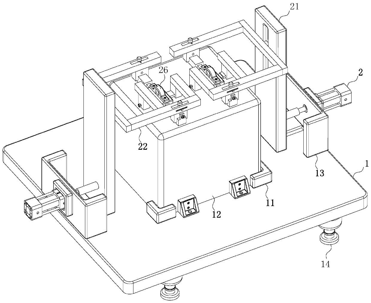
[0023] As an embodiment of the present invention, the lower surface of the base 1 is fixedly connected with evenly arranged support bases 14; When working, when the capacitor 12 needs to weld the lifting lug 26 accessories, in order to further improve the position accuracy of the lifting lug 26 welding, the support base 14 that is evenly arranged is fixed on the lower surface of the base 1, and then the support base 14 is placed on a relatively flat workbench, and then the adjusting ring is twisted manually or with a wrench, so that the adjusting ring is rotated up and down, and then the height of the support seat 14 is adjusted, so that the base 1 is completely horizontally placed, so it is effective This reduces the machining accuracy of the workbench and the accuracy requirements for horizontal placement, and further improves the accuracy of welding the lifting lug 26 on the surface of the capacitor 12 .

[0024] As an embodiment of the present invention, the first limit bl...


PUM


Abstract

The invention belongs to the technical field of welding tool clamps, and particularly relates to a high-voltage direct-current supporting capacitor shell accessory welding tool clamp. A base, air cylinders and connecting rods are included. The positions, close to the left side face and the right side face of the base, of the upper surface of the base are fixedly connected with installing frames. The side faces of the sides, back onto each other, of the two installing frames are fixedly connected with the air cylinders. Piston rods of the air cylinders are fixedly connected with sliding plates.The positions, close to the upper surfaces of the corresponding sliding plates, of the side faces of the opposite sides of the sliding plates are provided with second sliding grooves. Supports are inup-down sliding connection in the second sliding grooves. The positions, located at the left side and right side positions of a lifting lug, of the inner surface of one side of each support are fixedly connected with the connecting rods. The problems that in the prior art, the high-voltage direct-current supporting capacitor shell outer welded lifting lug accessory position deflection degree is large, consistency is low, the appearance quality is poor, and high unicity exists for lifting lug position limiting through a clamp are effectively solved; and automatic limiting is effectively achieved, and practicability is high.

Description

technical field [0001] The invention belongs to the technical field of welding fixtures, in particular to a welding fixture for high-voltage DC support capacitor shell accessories. Background technique [0002] Capacitors are electronic components that are widely used in electronic equipment. DC support capacitors, also known as DC-Link capacitors, are a type of passive devices. Polypropylene film dielectric DC support capacitors are mainly used now, which have high withstand voltage and durability. Large current, low impedance, low inductance, small capacity loss, small leakage current, good temperature performance, fast charging and discharging speed, long service life, good safety and explosion-proof stability, non-polarity and convenient installation, etc., are widely used in the power electronics industry , The support capacitor used for power transmission and transformation occupies an important position in the power transmission system. The high-voltage DC support cap...

Claims


Application Information

Patent Timeline
IPC IPC(8): B23K37/04
CPCB23K37/0443B23K2101/36
Inventor 王志林钱叶龙卢文定
Owner TONGLING LONGJIA ELECTRICAL
Why Eureka
Try Eureka