A spherical grinding device for a ball core

A technology of spherical surface grinding and ball core, applied in the direction of grinding driving device, grinding/polishing safety device, spherical grinding machine, etc., can solve the problems of inability to process, low efficiency, troublesome use, etc., to improve production efficiency and use Convenience, adjustment and quick effect

Active Publication Date: 2020-09-29
顶红科技发展(浙江)有限公司
View PDF5 Cites 2 Cited by
  • Summary
  • Abstract
  • Description
  • Claims
  • Application Information

AI Technical Summary

Problems solved by technology

[0004] When the spherical surface of the existing ball valve is ground, the trunnion is generally clamped by a fixture, and the fixture and the ball core are driven by the motor to rotate, and the grinding head is attached to the grinding work. However, this grinding device only It can process a ball core, and the grinding head must be replaced immediately when the grinding head is worn out. During the replacement period, processing cannot be performed, and the position accuracy of the replaced grinding head needs to be corrected, which is very troublesome to use and low in efficiency.

Method used


Image

  • A spherical grinding device for a ball core
  • A spherical grinding device for a ball core
  • A spherical grinding device for a ball core

Examples


Embodiment 1

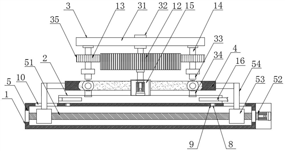
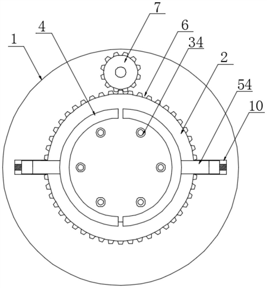
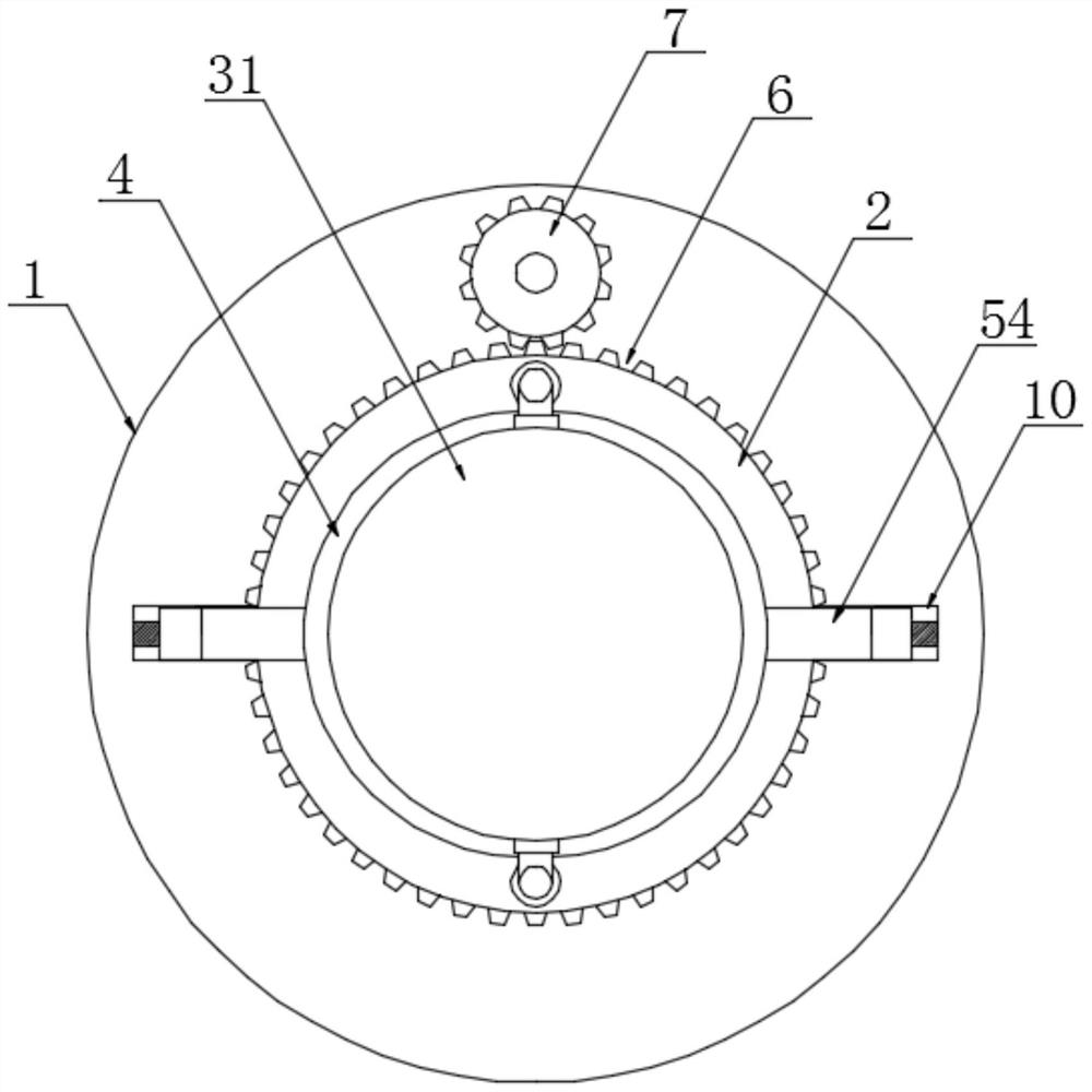
[0031] Refer to the attached Figure 1-5 In this embodiment, a spherical surface grinding device for a ball valve core includes a workbench 1, a rotary table 2 is provided on the top of the worktable 1, and a multi-ball core clamping mechanism 3 is provided on the top of the rotary table 2. The two sides of the multi-core clamping mechanism 3 are respectively equipped with grinding outer plates 4, and the two grinding outer plates 4 are driven by the reciprocating mechanism 5 to perform reciprocating linear motion, and are used for grinding the ball fixed by the multi-ball core clamping mechanism 3. Spherical core surface, the outer wall of the rotary table 2 is provided with a tooth groove 6, and the rear side of the rotary table 2 is provided with a driving gear 7 meshing with the tooth groove 6, and the driving gear 7 is driven by a servo motor;

[0032] The multi-core clamping mechanism 3 includes a lifting table 31, an electric telescopic rod 32, an upper clamp 33, a lowe...

Embodiment 2

[0046] Refer to the attached Figure 6-7 , the inside of the turntable 2 is provided with an exhaust cavity 16, the slot 11 on the lower fixture 34 runs through the lower fixture 34 and communicates with the exhaust cavity 16, and the outer wall of the turntable 2 is provided with a plurality of exhaust holes 17 , the exhaust hole 17 communicates with the exhaust cavity 16, the exhaust cavity 16 is arranged in a ring shape, one end of the exhaust cavity 16 is connected to the exhaust pipe 18, and one end of the exhaust pipe 18 runs through the rotary table 2 and is connected by a bellows Vacuum cleaner.

[0047] The specific implementation scene is: the present invention sets up the embedded groove 11 connected with the air suction chamber 16 on the lower fixture 34, the vacuum cleaner works, and the air inside the air suction chamber 16 is extracted through the bellows and the air suction pipe 18, and a negative pressure is formed in the air suction chamber 16 , when the sph...


PUM


Abstract

The invention discloses a spherical surface grinding device for ball valve cores and particularly relates to the field of ball valve element machining. The spherical surface grinding device for the ball valve cores comprises a worktable, a rotating table is arranged at the top of the worktable, a multi-ball-core clamping mechanism is arranged at the top of the rotating table, outer grinding platesare arranged on the two sides of the multi-ball-core clamping mechanism respectively, the two outer grinding plates are driven through a reciprocating mechanism to do reciprocating linear movement and are used for grinding the spherical surfaces of ball cores fixed by the multi-ball-core clamping mechanism, tooth grooves are formed in the outer wall of the rotating table, and a driving gear engaged with the tooth grooves is arranged on the rear side of the rotating table. The spherical surface grinding device can grind multiple ball cores at the same time, and the working efficiency is greatly improved; besides, when the contact faces of the outer grinding plates and the ball cores are worn, position offset replacement of multiple ball core clamps can be achieved simply by driving the rotating table through the driving gear, and the grinding faces of the outer grinding plates and the ball cores are replaced; and the grinding device is very convenient to use, adjustment is quick, and the machining efficiency and the precision of the ball cores are not influenced.

Description

technical field [0001] The embodiment of the present invention relates to the field of ball valve core processing, in particular to a spherical surface grinding device for a ball valve core. Background technique [0002] The ball valve is one of the most widely used valves. Its working principle is the same as that of the plug valve. It is opened and closed by rotating the valve core, but it is lighter than the plug valve and relatively small in size. It can be made into a large-diameter ball valve. The ball valve has reliable sealing, simple structure and convenient maintenance. The sealing surface and the ball are often in a closed state, which is not easy to be eroded by the medium, so it is widely used in petroleum, chemical, metallurgical and other industries. [0003] A ball valve generally includes a valve body, a valve seat, and a ball placed in the seat. The ball generally includes two parallel and symmetrical end faces. The distance between the two end faces is sma...

Claims


Application Information

Patent Timeline
Patent Type & Authority Patents(China)
IPC IPC(8): B24B11/04B24B27/00B24B41/06B24B47/12B24B55/06B24B55/12
CPCB24B11/04B24B27/0023B24B27/0076B24B41/061B24B47/12B24B55/06B24B55/12
Inventor 苏忠根陈海哨王术新
Owner 顶红科技发展(浙江)有限公司
Why Eureka
Try Eureka