Ultrasonic vibration type front windshield
A front windshield and ultrasonic vibration technology, applied in the direction of windshield, vehicle cleaning, windows, etc., can solve the problems of limited wiper cleaning limit, blurred driving line of sight, affecting safe driving, etc., to achieve fast defogging process and ensure Driving safety and low energy consumption
- Summary
- Abstract
- Description
- Claims
- Application Information
AI Technical Summary
Problems solved by technology
Method used
Image
Examples
specific Embodiment approach 1
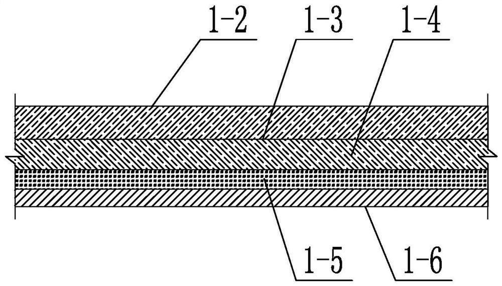
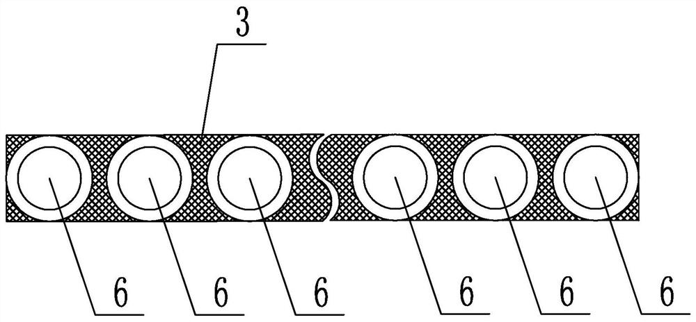
[0028] Specific implementation mode one: combine figure 1 , figure 2 , image 3 , Figure 4 and Figure 5 Describe this embodiment. This embodiment includes a composite glass body 1 and an ultrasonic vibration assembly 2. The composite glass body 1 includes an inner glass body 1-2, an explosion-proof layer 1-3, an outer glass body 1-4, a noise reduction layer 1-5 and The vibrating plate 1-6, the inner glass body 1-2, the explosion-proof layer 1-3, the outer glass body 1-4, the noise reduction layer 1-5 and the vibrating plate 1-6 are sequentially bonded together from the inside to the outside, The ultrasonic vibration assembly 2 includes a connecting band 3 and several ultrasonic transducers 6, the connecting band 3 is arranged on the composite glass body 1 along the peripheral direction of the composite glass body 1, and several ultrasonic transducers 6 are arranged along the length direction of the connecting band 3. Clothed on the connecting belt 3, each ultrasonic tra...
specific Embodiment approach 2
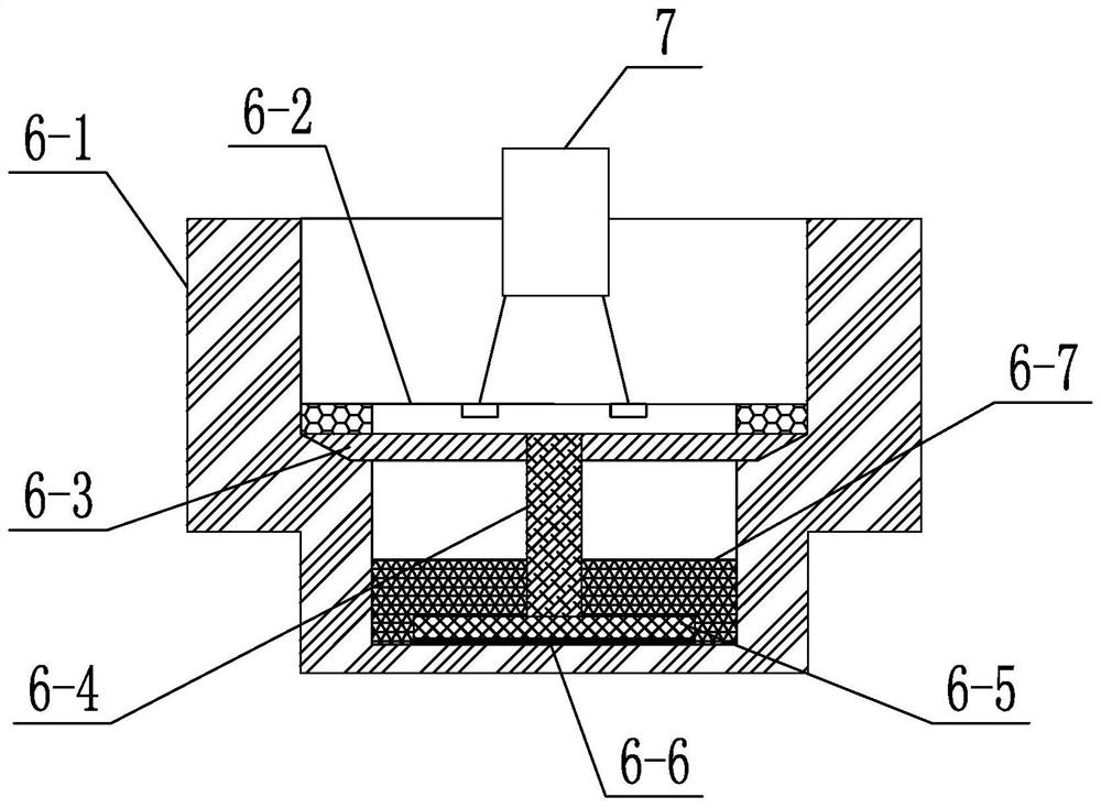
[0032] Embodiment 2: This embodiment is a further limitation of Embodiment 1. The ultrasonic transducer 6 includes a housing 6-1, a conductive sheet 6-2, a wiring board 6-3, a conductive column 6-4, and a piezoelectric sheet 6. -5 and heat insulating sheet 6-6, the lower end of the shell 6-1 is a sealed end, the upper end of the shell 6-1 is an open end set with the signal cable 7, and the inside of the shell 6-1 is horizontal from top to bottom A conductive sheet 6-2, a wiring board 6-3, a piezoelectric sheet 6-5 and a heat insulating sheet 6-6 are provided, and a conductive column 6-4 is arranged between the wiring board 6-3 and the piezoelectric sheet 6-5, The signal cable 7 passes through the open end of the shell 6-1 and is connected to the conductive sheet 6-2, and the outer end surface of the sealed end of the shell 6-1 is a radiation surface.
[0033] Further, the shape of the optimal radiating surface obtained through the sample test is circular, the optimal diameter ...
specific Embodiment approach 3
[0036] Embodiment 3: This embodiment is a further limitation of Embodiment 1 or 2. The bottom of the housing 6-1 is provided with a rubber sleeve 6-7, and the rubber sleeve 6-7 is set on the conductive column 6-4 and the piezoelectric sheet. On 6-5, the top of rubber sheath 6-7 cooperates with the lower end clearance of wiring board 6-3.
[0037] In this embodiment, the rubber sheath 6-7 is set on the conductive post 6-4 and the piezoelectric sheet 6-5, so as to cover the conductive post 6-4 and the piezoelectric sheet 6-5. The rubber sleeve 6-7 is sleeved on the conductive post 6-4, and the length covering the conductive post 6-4 does not exceed half of the total length of the conductive post 6-4.
[0038] In this embodiment, the rubber sleeve 6-7 is used to absorb the noise generated by the vibration of the radiating surface and give feedback force to the radiating vibration surface, so as to ensure that the vibrating piece 1-6 always maintains high-frequency vibration.
PUM
 Abstract
Description
Claims
Application Information
 - R&D
- Intellectual Property
- Life Sciences
- Materials
- Tech Scout
- Unparalleled Data Quality
- Higher Quality Content
- 60% Fewer Hallucinations
Browse by: Latest US Patents, China's latest patents, Technical Efficacy Thesaurus, Application Domain, Technology Topic, Popular Technical Reports.
© 2025 PatSnap. All rights reserved.Legal|Privacy policy|Modern Slavery Act Transparency Statement|Sitemap|About US| Contact US: help@patsnap.com


