Food processing plastic chain plate production line

A food processing and assembly line technology, applied in the direction of transportation and packaging, conveyors, etc., can solve problems such as softening and deformation

Inactive Publication Date: 2020-05-08
王国义
View PDF0 Cites 3 Cited by
  • Summary
  • Abstract
  • Description
  • Claims
  • Application Information

AI Technical Summary

Problems solved by technology

[0007] In order to solve the above-mentioned technical food in the production process, there will be a certain temperature in itself. When the food with a certain temperature is placed on the plastic chain plate, it is easy to cause it to soften and deform when

Method used


Image

  • Food processing plastic chain plate production line
  • Food processing plastic chain plate production line
  • Food processing plastic chain plate production line

Examples


Embodiment 1

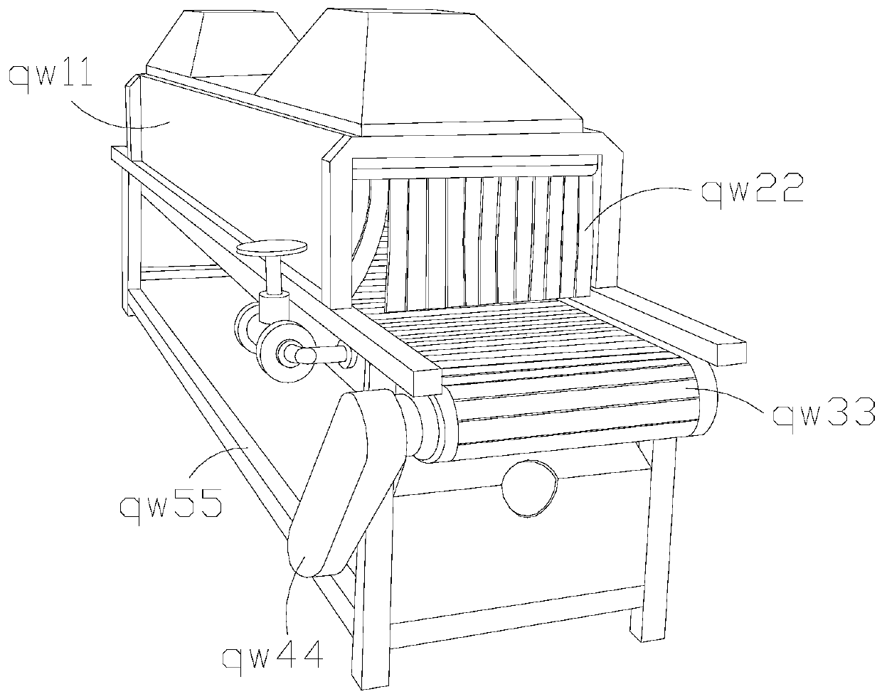
[0032] as attached figure 1 to attach Figure 5 Shown:

[0033] The invention provides a food processing plastic chain plate assembly line, the structure of which includes a food processing box qw11, a curtain qw22, a plastic chain plate qw33, a side belt body qw44, and a support rod qw55.

[0034] The curtain qw22 is connected to the food processing box qw11, the bottom of the food processing box qw11 is welded to the upper surface of the support rod qw55, and the side belt body qw44 is connected to the plastic chain plate qw33.

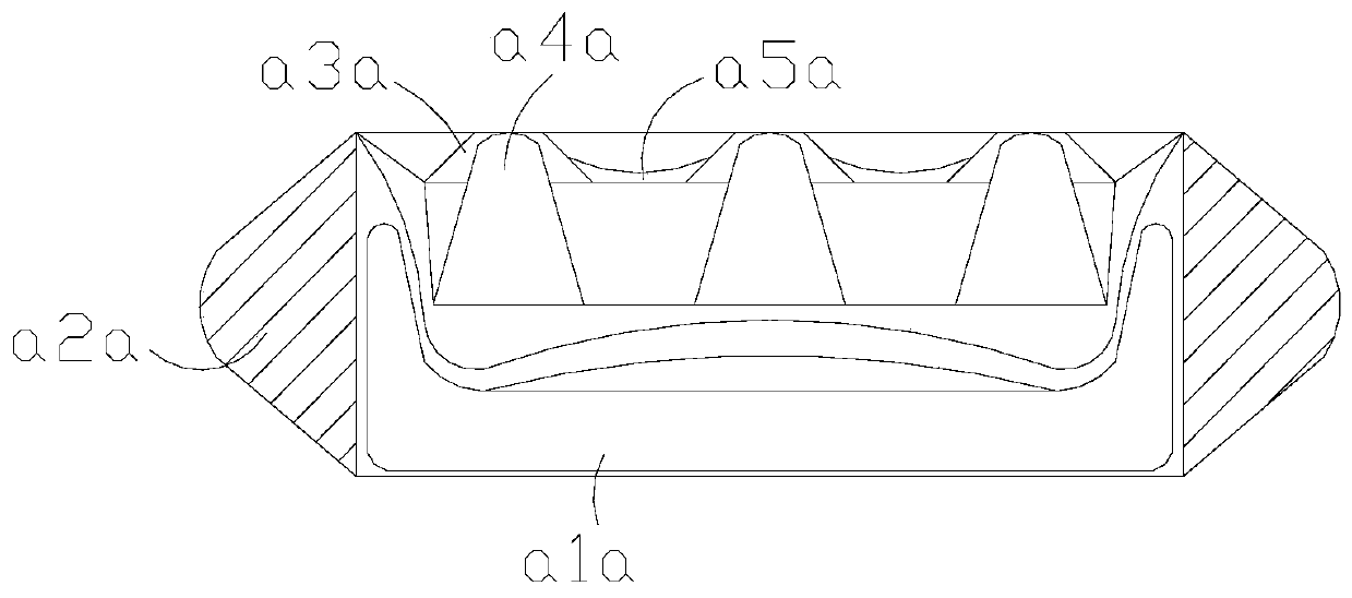
[0035] Wherein, the plastic chain plate qw33 includes a bottom hard core a1a, a side connecting block a2a, a convex head a3a, an inner core a4a, and a concave arc a5a. The bottom hard core a1a is arranged below the inner core a4a, and the inner The abutment core a4a is connected with the convex head a3a, the outer surface of the convex head a3a is equipped with a concave arc a5a, the bottom hard core a1a is embedded in the side joint block a2a, an...

Embodiment 2

[0042] as attached Image 6 to attach Figure 8 Shown:

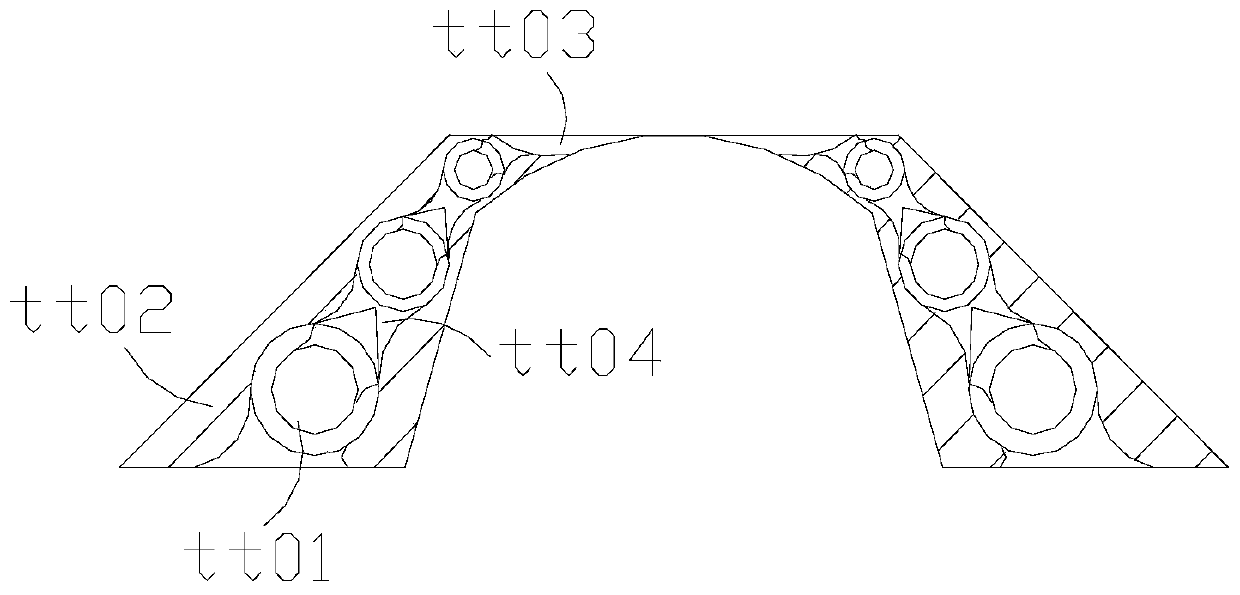
[0043] Wherein, the bottom hard core a1a includes a pullback angle ss01, a support block ss02, a protective layer ss03, and a slow force pulling core ss04, the slow force pull core ss04 is connected with the pull back angle ss01, and the support block ss02 is attached to the protective On the outer surface of the layer ss03, the support block ss02 has a semi-arc structure, and the return angle ss01 has a triangular structure, and the return force angle ss01 bears external forces in a large area and is evenly distributed. The force is in the state of stretching and pulling, and it acts as a pulling back. The supporting block ss02 supports the general range of the whole.

[0044] Wherein, the return force angle ss01 includes an elliptical ball www1, an arc extension www2, a rubber pull block www3, and a bend www4. The ellipse ball www1 is embedded inside the arc extension www2. Blocks www3 are connected, the outer surfa...


PUM


Abstract

The invention discloses a food processing plastic chain plate production line. The food processing plastic chain plate production line structurally comprises a food processing box, a blocking curtain,plastic chain plates and a side belt body. The blocking curtain is connected with the food processing box. An adhesion concave opening of each convex jacking head abuts against food, an internal jacking and scattering ball in each plastic chain plate jacks the whole food and keeps the highest point, the outer surface of the food is jacked, the food has a highest point, and the two sides graduallyslide down; connection between the constant force uniformizing balls is achieved through space supporting rubber, internal hard angle cores jack the overall form, the food is fixed through point positions, and heat of the food can be appropriately dissipated and prevented from gathering and softening the chain plates; return corners drag a protective layer to bear the overall bending force, whenthe return corners are forced apart and force is applied to the return corners, the return corners bear external force at a large area and make the external force to be evenly distributed, rubber pulling blocks of the return corners are bent along with the radian of curved openings, so that when the chain plate deforms and moves at a bending angle, the range of the chain plate can be limited, andthe chain plate can be pulled and reset in a following process.

Description

technical field [0001] The invention belongs to the field of chain plate assembly lines, and more specifically relates to a plastic chain plate assembly line for food processing. Background technique [0002] The chain plates on the chain plate assembly line are made of various materials, such as stainless steel, plastic, etc. The plastic chain plate assembly line is relatively light overall, and the force required for transmission is relatively small, so it can be applied to food production lines that need to be transported quickly. [0003] Based on the inventor's discovery above, the existing plastic chain plate assembly line mainly has the following deficiencies, such as: [0004] 1. During the production process, the food itself will have a certain temperature. When the food with a certain temperature is placed on the plastic chain plate, it is easy to soften and deform if it is placed for a long time. [0005] 2. When the plastic chain plate is deformed and continues ...

Claims


Application Information

Patent Timeline
IPC IPC(8): B65G17/06B65G17/30B65G17/46B65G21/08
CPCB65G17/065B65G17/30B65G17/46B65G21/08B65G2201/0202
Inventor 王国义
Owner 王国义
Why Eureka
Try Eureka