
Fluidized mining method for on-situ pyrolyzed gas of high gas coal seam

A technology of in-situ pyrolysis and mining methods, applied in gas emission, mining equipment, mining equipment, etc., can solve problems such as poor disaster controllability, spontaneous combustion of coal or gas explosion, and reduced extraction efficiency.

Active Publication Date: 2020-05-08
CHINA UNIV OF MINING & TECH
View PDF5 Cites 9 Cited by
  • Summary
  • Abstract
  • Description
  • Claims
  • Application Information

AI Technical Summary

Problems solved by technology

[0003] However, conventional coal seam permeability enhancement methods have certain defects. For example, hydraulic fracturing technology needs to provide a large volume of water resources, which increases the water pressure in water-scarce areas. For coal seams with strong water sensitivity, a large amount of After the pressure water is injected into the coal seam, it will cause water lock reaction in the coal seam inner pore and fracture structure, and block the CH 4 gas flow channels, greatly reducing the CH 4 Drainage efficiency; heat injection technology requires the use of a large amount of water vapor, microwave radiation and other heating methods to increase the temperature in the coal seam, thereby producing many pore and fissure structures of different scales, promoting the desorption of adsorbed gas into free states, along the pore and fissure structures Seepage diffusion occurs, but there are also certain application limitations. For example, the water vapor or electric energy consumption required to increase the temperature of the coal body to reach the crushing temperature is extremely large, which lacks certain feasibility for field application; secondly, the high The temperature is easy to cause spontaneous combustion of coal or gas explosion, which has poor controllability of catastrophe

Method used


Image

  • Fluidized mining method for on-situ pyrolyzed gas of high gas coal seam
  • Fluidized mining method for on-situ pyrolyzed gas of high gas coal seam
  • Fluidized mining method for on-situ pyrolyzed gas of high gas coal seam

Examples


Embodiment Construction

[0024] An embodiment of the present invention will be further described below in conjunction with accompanying drawing:

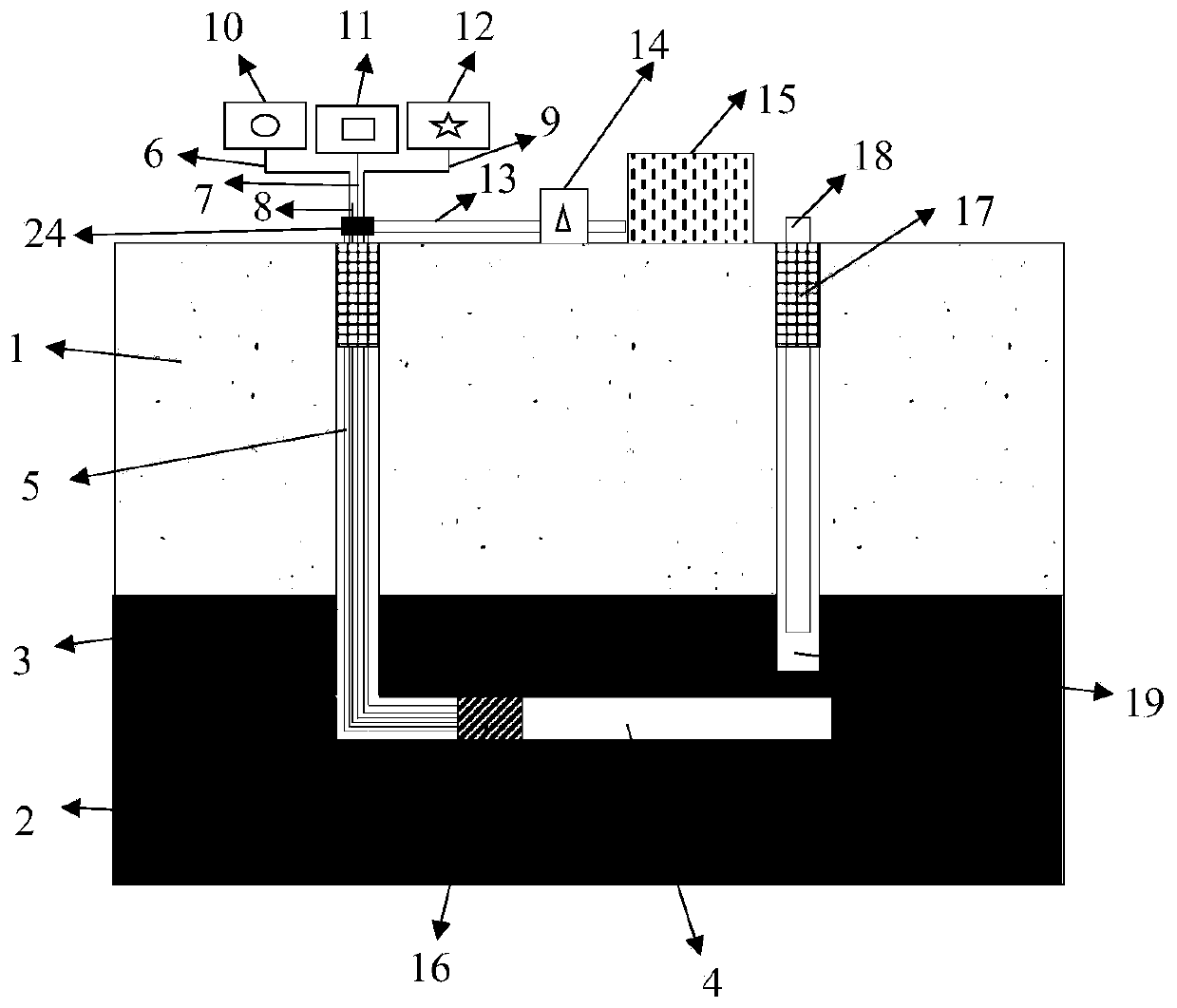
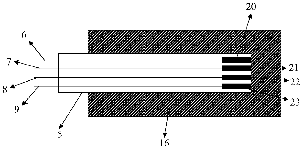
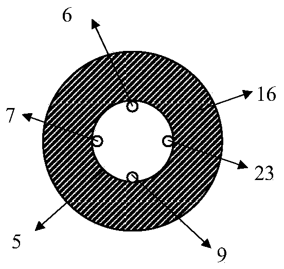
[0025] Such as figure 1 , figure 2 and image 3 As shown, the in-situ pyrolysis gas fluidization mining method of high gas coal seams of the present invention uses a multifunctional assembly device 16, and a temperature sensor 20, a gas detector 21, and a sparker head are respectively fixed in the multifunctional assembly device 16. 22 and a pressure sensor 23, the multifunctional assembly device 16 is arranged on the head of the copper tube 5, and the copper tube 5 is provided with a temperature sensor line 6, a gas detector line 7, a sparker line 8 and a pressure sensor line 9, and the copper tube 5. A temperature monitoring device 10, a multi-component gas monitoring device 11 and a pressure monitoring device 12 are provided at the tail. The other spaces in the copper pipe 5 provide air flow space. The air flow space of the copper pipe 5 passes throug...


PUM


Abstract

The invention relates to a fluidized mining method for on-situ pyrolyzed gas of a high gas coal seam. The method is suitable for being used in a low-permeability, low-temperature strong oxidability and high gas content coal seam or a remnant coal seam in a closed goaf. The method comprises the following steps of drilling a horizontal drilling well and a gas extraction drilling well from the groundto a target coal seam or the remnant coal same in the closed goaf; generating a lot of cracks around the horizontal drilling well by way of detonation; sealing a hole of a shaft; injecting air at a proper flow rate into the horizontal drilling well; after the target coal seam or the remnant coal seam is in contact with a small amount of air for a certain time, carrying out smoldering on the coalseam by using a fire striker, wherein raised temperature can induce penetration among a lot of multi-scale hole cracks to accelerate desorption of adsorbed gas in the coal seam, and meanwhile, CO2 gasgenerated by smoldering can displace the adsorbed gas in a coal matrix effectively, so that the gas seeps and is diffused along a crack network; and finally, carrying out negative pressure extractionby the gas extraction drilling well. The method is high in feasibility and simple to operate, and can achieve efficient utilization of a coal resource to the maximum extent.

Description

technical field [0001] The invention relates to an in-situ pyrolysis gas fluidization mining method for high-gas coal seams, especially suitable for high-gas coal seam in-situ pyrolysis coal seams with low permeability, low-temperature strong oxidation, high gas content coal seams or leftover coal seams in closed goafs. Solution gas fluidization mining method. Background technique [0002] With the continuous increase of mining depth, high ground stress makes high-strength coal seams generally have the characteristics of high degree of metamorphism, compact structure, low porosity, and poor permeability. Due to the limitation of mining technology, there are usually a large number of residual coal seams in many closed goafs. . Correspondingly, the coal seam to be mined needs to meet the construction sequence of gas drainage first and then coal mining. On the other hand, the remaining coal seam contains a large amount of gas. Anti-reflection methods such as fracturing techno...

Claims


Application Information

Patent Timeline
Patent Type & Authority Applications(China)
IPC IPC(8): E21F7/00E21F17/00E21F17/18
CPCE21F7/00E21F17/00E21F17/18
Inventor 翟成徐吉钊辛海会宋正昶
Owner CHINA UNIV OF MINING & TECH
Learn More