Machine furnace deeply coupled thermodynamic system of thermal power generating unit

A technology of thermal power units and thermal systems, applied in the direction of machines/engines, mechanical equipment, steam engine devices, etc., can solve problems such as limited energy saving effects, and achieve the effect of improving power generation efficiency

Inactive Publication Date: 2020-05-08
DONGFANG TURBINE CO LTD
View PDF3 Cites 1 Cited by
  • Summary
  • Abstract
  • Description
  • Claims
  • Application Information

AI Technical Summary

Problems solved by technology

[0004] However, since the exhaust gas temperature of the boiler is about 180°C, the energy-saving effect of the flue gas waste heat utilization technology is limited, and the energy-saving potential of coal-fired power plants needs to be further explored.

Method used


Image

  • Machine furnace deeply coupled thermodynamic system of thermal power generating unit
  • Machine furnace deeply coupled thermodynamic system of thermal power generating unit

Examples


Embodiment 1

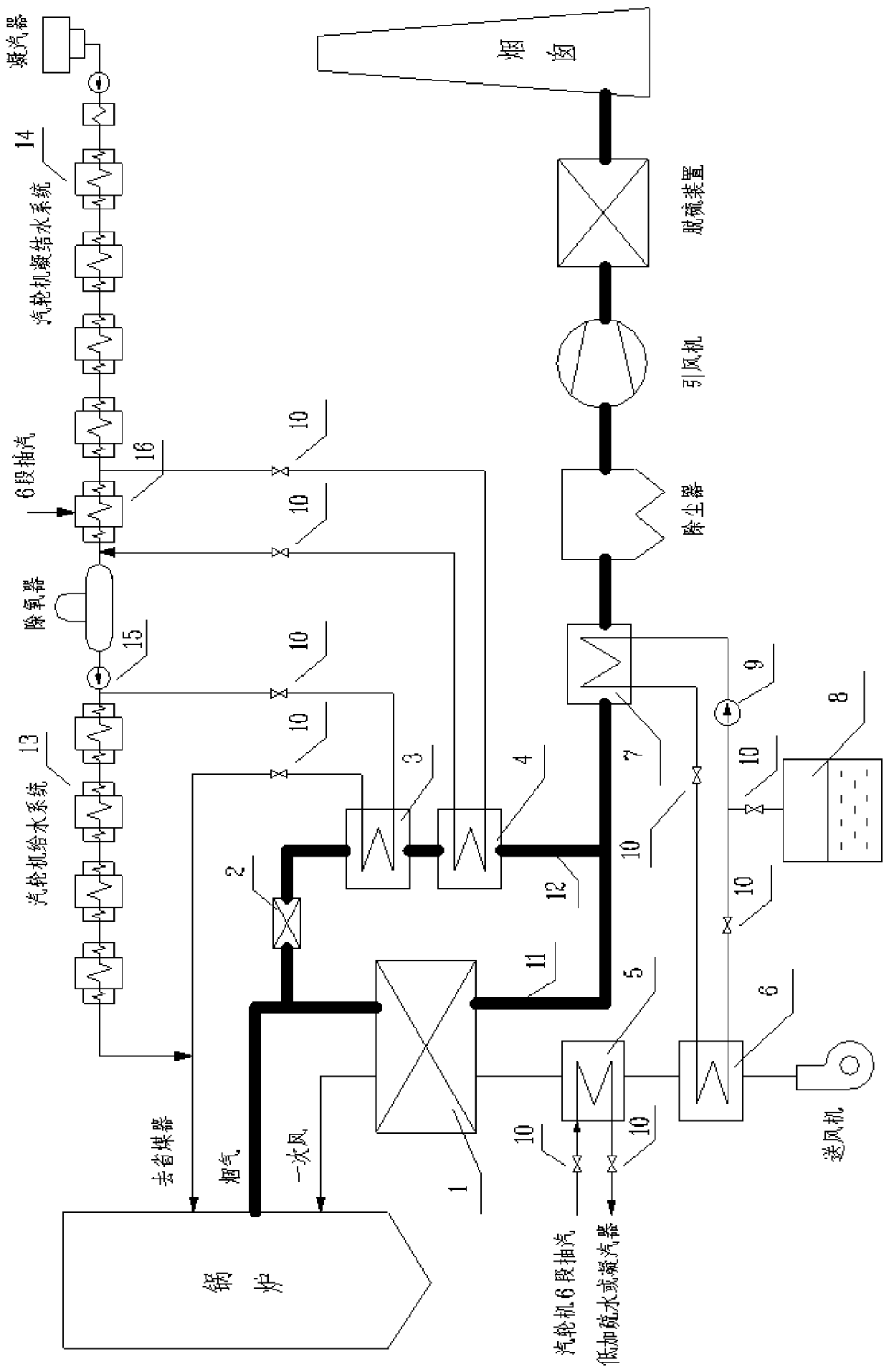
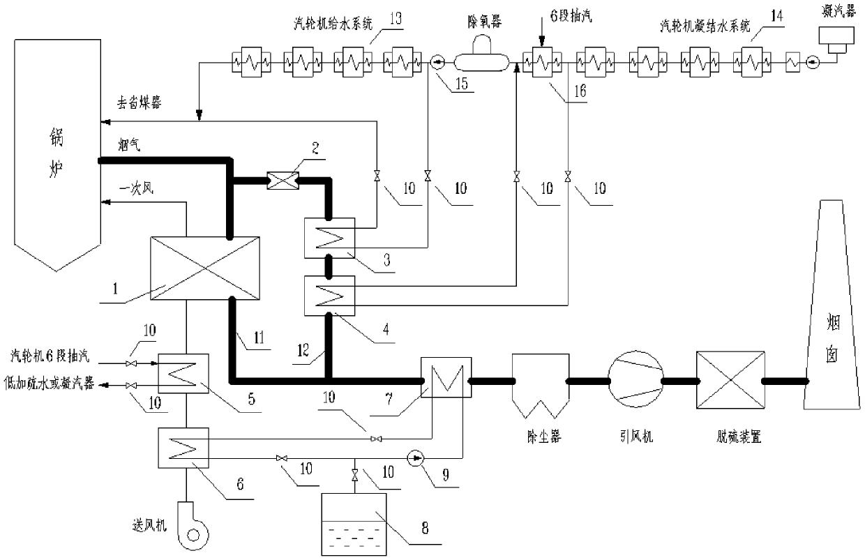
[0022] Such as figure 1 As shown, in this embodiment, a deep coupling thermodynamic system of a thermal power unit includes a boiler, a main flue 11, a dust collector, an induced draft fan, a desulfurization device, and a chimney that are sequentially connected in accordance with the gas flow direction. The flue 11 is connected in parallel with a bypass flue 12, the main flue 11 is provided with an air preheater 1, and the boiler is communicated with a primary air duct capable of exchanging heat with the air preheater 1, and the bypass The flue 12 is provided with a waste heat recovery system.

[0023] The flue gas coming out of the boiler is divided into two paths, one goes into the main flue 11 , and the other goes into the bypass flue 12 . The primary air pipe delivers air to the boiler, and the air in the primary air pipe is preheated by the air preheater 1 , so that the waste heat in the flue gas in the main flue 11 is utilized. The flue gas entering the bypass flue 12 ...

Embodiment 2

[0025] On the basis of the above embodiments, in this embodiment, a heat medium water heater 6 capable of heat exchange with the primary air duct is arranged between the air blower and the steam heater 5, and the main flue 11 and the A flue gas waste heat recovery device 7 is arranged between the dust collectors, and the flue gas waste heat recovery device 7 communicates with the heat medium water heater 6 through a pipeline circulation, and the flue gas waste heat recovery device 7 communicates with the heat medium water heater 6 through a pipeline A circulating pump 9 and a regulating valve 10 are arranged on it.

[0026] The heat medium water heater 6, the flue gas waste heat recovery device 7, the water supply tank 8, the circulation pump 9 and the regulating valve 10 together form a closed cycle of flue gas waste heat recovery, and the flue gas in the air preheater 1 enters the flue gas after heat exchange In the gas waste heat recovery device 7, the heat medium water in ...

Embodiment 3

[0031] On the basis of the above embodiments, in this embodiment, the waste heat recovery system includes a high-pressure smoke-water heat exchanger 3 capable of heat exchange with the bypass flue 12, and the inlet of the high-pressure smoke-water heat exchanger 3 is connected with The feedwater pump 15 and the outlet of the high-pressure smoke-water heat exchanger 3 are connected with the boiler.

[0032] The feedwater pump 15 supplies water to the high-pressure flue-water heat exchanger 3. In the high-pressure flue-water heat exchanger 3, the water and the flue gas perform heat exchange, and the water after the heat exchange enters the economizer of the boiler to protect the bypass The heat of the flue gas in the flue 12 is recycled.

[0033] In this embodiment, the high-pressure smoke-water heat exchanger 3 is connected in parallel with a steam turbine water supply system 13 .

[0034] The outlet water of the feed water pump 15 is divided into two paths, one path enters th...


PUM


Abstract

The invention discloses a machine furnace deeply coupled thermodynamic system of a thermal power generating unit. The machine furnace deeply coupled thermodynamic system of the thermal power generating unit comprises a boiler, a main flue, a dust remover, an induced draft fan, a desulfurization device and a chimney which communicate with one another sequentially according to a gas flowing direction; the main flue is connected with a bypass flue in parallel; an air preheater is arranged on the main flue; the boiler communicates with a primary air pipeline capable of exchanging heat with an airpreheater; and a waste heat recovering system is arranged on the bypass flue. The machine furnace deeply coupled thermodynamic system of the thermal power generating unit has the following beneficialeffects: according to the scheme, cold air in the primary air pipeline is heated to a certain degree and then is fed into the air preheater, the replaced high-grade high-temperature flue gas enters the bypass flue, the high-temperature flue which is divided to enter the bypass flue heats feed water and condensed water, and higher-grade regenerative heat extraction steam is discharged and enters asteam turbine to apply work, so that cross and gradient utilization of energy is realized, and the power generation efficiency of a coal-fired power plant can be improved better compared with that inthe prior art.

Description

technical field [0001] The invention relates to the technical field of thermal power generation, in particular to a thermal power system deeply coupled with a furnace of a thermal power unit. Background technique [0002] Electricity is the most basic, cleanest, and most convenient form of energy in modern society. It is an important means of production and living for human beings, and plays an important role in supporting economic and social development. China's energy resource endowment has the characteristics of "rich in coal, short of oil, and low in gas", which determines that the structure of China's power industry is dominated by coal-fired power generation. Although affected by factors such as environmental protection and power structure reform, domestic non-fossil energy installed capacity has grown rapidly in recent years, and the proportion of thermal power installed capacity in electric power installed capacity has shown a slight decline year by year. However, th...

Claims


Application Information

Patent Timeline
Patent Type & Authority Applications(China)
IPC IPC(8): F01K27/00F01K21/00F01K13/00F01D15/10
CPCF01D15/10F01K13/00F01K21/00F01K27/00
Inventor 张晓东雷晓龙陈显辉井芳波刘晓燕唐丽丽张小波王松宋放放宋萍
Owner DONGFANG TURBINE CO LTD
Why Eureka
Try Eureka