A circuit and method for measuring ignition delay time of solid propellant
A solid propellant and ignition delay technology, which is applied in jet propulsion devices, rocket engine devices, machines/engines, etc., can solve the problems of measurement accuracy limitation and large picture error, and achieve error reduction, low cost of circuits and systems, and convenient recorded effect
- Summary
- Abstract
- Description
- Claims
- Application Information
AI Technical Summary
Problems solved by technology
Method used
Image
Examples
Embodiment 1
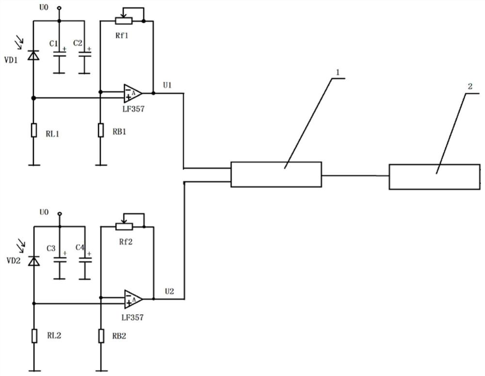
[0061] combine figure 1 , figure 2 , a circuit diagram for measuring the ignition delay time of solid propellants includes: power supply, 4 filter capacitors C 1 、C 2 、C 3 、C 4 , 2 photodiodes VD 1 , VD 2 , 2 reverse bias operational amplifier circuits, data acquisition card, computer test software. Connect the positive pole of the power supply to the photodiode VD 1 , the anode of the operational amplifier LF357 is connected in turn, and the photodiode VD 1 Connect a grounding resistor RL in parallel with the operational amplifier LF357 1 . Connect the negative pole of the operational amplifier LF357 to the feedback resistor Rf 1 Connected at one end, Rf 1 The other end is connected to the data acquisition card CH 1 aisle. Operational amplifier LF357 negative pole and feedback resistor Rf 1 A grounding resistor RB is connected in parallel in the middle 1 . Connect the filter capacitor C in parallel at both ends of the power supply 1 , C 2 .
[0062] Connec...
PUM
 Abstract
Description
Claims
Application Information
 - R&D
- Intellectual Property
- Life Sciences
- Materials
- Tech Scout
- Unparalleled Data Quality
- Higher Quality Content
- 60% Fewer Hallucinations
Browse by: Latest US Patents, China's latest patents, Technical Efficacy Thesaurus, Application Domain, Technology Topic, Popular Technical Reports.
© 2025 PatSnap. All rights reserved.Legal|Privacy policy|Modern Slavery Act Transparency Statement|Sitemap|About US| Contact US: help@patsnap.com


