
A metal stamping part

A technology of stamping parts and hardware, which is applied in the field of metal stamping parts, can solve the problems of full-plastic oil filter toothing, transmission gear or oil filter damage, etc., and achieves heat-resistant deformation, long service life, and equipment investment saving cost effect

Active Publication Date: 2021-04-02
茂森精艺金属(苏州)有限公司
View PDF9 Cites 0 Cited by
  • Summary
  • Abstract
  • Description
  • Claims
  • Application Information

AI Technical Summary

Problems solved by technology

[0005] In order to make up for the deficiencies of the existing technology and solve the existing technology, the all-plastic oil filter is inside the high-temperature gearbox and is deformed by heat. Due to the high compactness of the design in the automobile gearbox, when the automobile gearbox transmission gear is high-speed During operation, the deformed all-plastic oil filter is prone to gearing, causing problems such as damage to the transmission gear or the oil filter. A metal stamping part proposed by the invention

Method used


Image

  • A metal stamping part
  • A metal stamping part
  • A metal stamping part

Examples


Embodiment approach

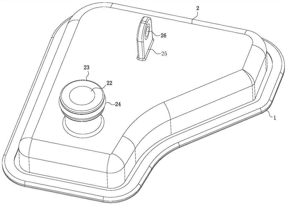
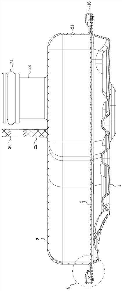
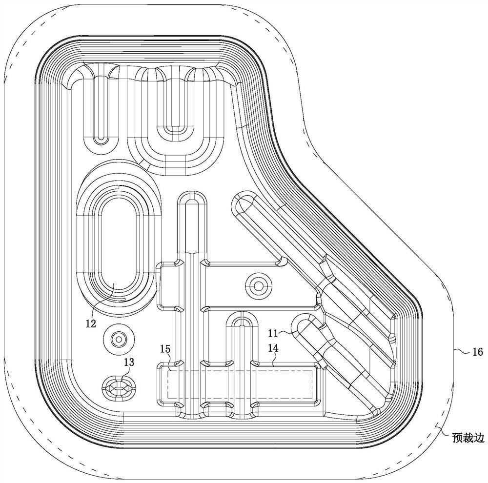
[0025] As an embodiment of the present invention, the cover plate 1 is punched with uniformly arranged pressing bosses 31 on one side of the housing 2, and the pressing bosses 31 are located near the bending position of the flange 16 The pressing boss 31 is designed with a trapezoidal ring structure; during work, since the connection position of the cover plate 1 and the opposite side of the housing 2 are planes, the filter paper 3 is pressed on the cover plate 1 and the housing 2 In between, the pulling force is difficult to control, and the pulling force of the filter paper 3 may be insufficient in some cases. However, since the filter paper 3 is located in the cavity 21 between the cover plate 1 and the housing 2, batch testing cannot be realized, and the testing process It will also cause damage to the filter paper 3, so the pulling force and quality of the filter paper 3 are unstable. By stamping the side of the cover plate 1 relative to the housing 2, there are evenly arr...


PUM


Abstract

The invention belongs to the technical field of hardware stamping, and particularly relates to a hardware stamping part. The hardware stamping part comprises a cover plate, a shell and filter paper, wherein a turnup on the upper surface of the cover plate covers the shell; the same filter paper is jointly pressed and connected between the cover plate and the shell; an oil outlet is formed in a position, away from an oil inlet of the cover plate, of the upper surface of the shell; a joint is fixedly connected to the outer surface, at a position of the oil outlet, of the shell; an O-shaped ringis fixedly connected to a position, close to the upper end surface of the joint, of the outer arc surface of the joint; a connecting seat is fixedly connected to a position, away from the joint, at the upper surface of the shell; and a nest is pre-embedded in the connecting seat. The problems that a full-plastic engine oil filter is prone to deforming when being heated in a high-temperature gearbox and prone to gear collision when a variable gear runs at a high speed in the prior art are solved, binding manufacturing process is achieved without ultrasonic welding, equipment investment cost isgreatly saved, and the quality is stable.

Description

technical field [0001] The invention belongs to the technical field of metal stamping, in particular to a metal stamping part. Background technique [0002] Hardware is a part processed from steel or some non-ferrous metals. Processing methods: cold / hot stamping, extrusion, rolling, welding, cutting, etc., including other processes, with a relatively wide definition; stamping parts are the most used in hardware processing It refers to the molds for steel / non-ferrous metals and other sheet materials at room temperature, which are formed into specified shapes by the pressure required for processing by the press, including some electronic devices, auto parts, decorative materials, etc. We usually say Stamping parts generally refer to cold stamping parts, that is, stamping hardware materials directly with molds. [0003] In the prior art, the all-plastic oil filter is inside the high-temperature gearbox and is deformed by heat. Due to the high compactness of the design in the a...

Claims


Application Information

Patent Timeline
Patent Type & Authority Patents(China)
IPC IPC(8): F16H57/04F16N39/06
CPCF16H57/0404F16N39/06F16N2039/007
Inventor 孙康康丁赛赛孙信
Owner 茂森精艺金属(苏州)有限公司
Learn More