
System and method for realizing synchronous control of multiple targets in deflagration experiment test system

A technology of synchronous control and testing system, which is applied in the field of safety science and technology, can solve the problems of the wave front arrival time at the observation window, the flame front arrival time at the observation window, etc., to ensure accuracy, comprehensive and accurate research results, and ensure vacuum degree Effect

Pending Publication Date: 2020-05-08
NORTH CHINA INST OF SCI & TECH
View PDF0 Cites 12 Cited by
  • Summary
  • Abstract
  • Description
  • Claims
  • Application Information

AI Technical Summary

Problems solved by technology

However, when the shock tube cooperates with the ultra-high-speed laser schlieren and transient spectrum test system for microscopic flow field testing, it involves time-scale control problems of multiple targets with large time differences, such as spark ignition response time, shock front arrival Observation window time, flame front arrival time at the observation window, control response time of inert flame retardant injection system, transient spectrum ICCD camera electronic shutter response time and ultra-high-speed camera CCD electronic shutter response time, etc.

Method used


Image

  • System and method for realizing synchronous control of multiple targets in deflagration experiment test system
  • System and method for realizing synchronous control of multiple targets in deflagration experiment test system
  • System and method for realizing synchronous control of multiple targets in deflagration experiment test system

Examples


Embodiment

[0074] In this embodiment, 8 groups of tests are performed on the response time of the high-voltage ignition system.

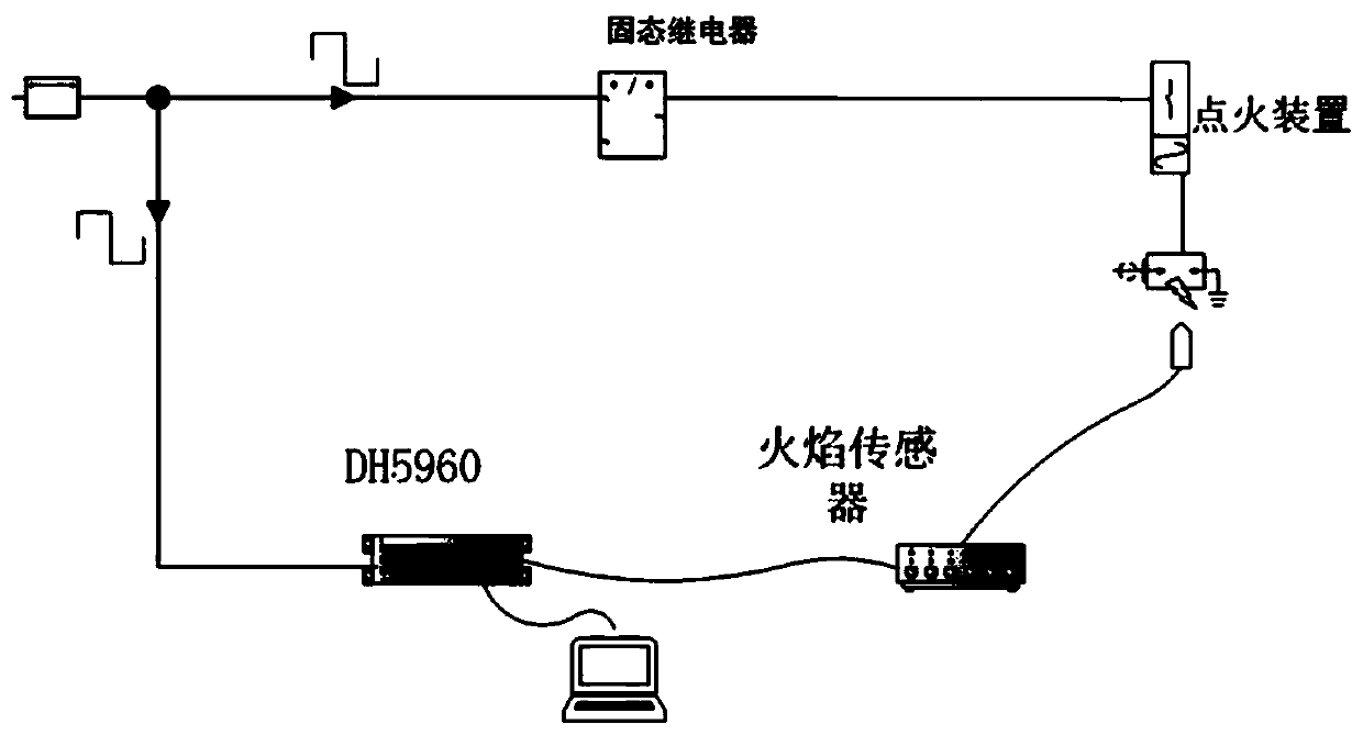
[0075] As shown in Figure 5, it is the measured signal of the response time of the high-voltage ignition system, in which the ignition voltage is 5000V, the sampling frequency of the data acquisition card is 1MHz, the flame signal sensitivity is 1mv / mv, the TTL signal is 10mv / mv, the trigger mode is signal trigger, and the signal of channel 07 is TTL level signal, channel 09 is EDM signal. The above experiments were repeated, and the data are shown in Table 2:

[0076] Table 2 High voltage ignition system discharge response time t 1 Experimental data

[0077] Experiment number response time t 1 / μs

Experiment number response time t 1 / μs

1 26 5 23 2 24 6 24 3 22 7 20 4 21 8 22

[0078] The average value of the discharge response time of the high-voltage ignition system measured by the 8 groups of exper...


PUM

PropertyMeasurementUnit
lengthaaaaaaaaaa
diameteraaaaaaaaaa
lengthaaaaaaaaaa

Abstract

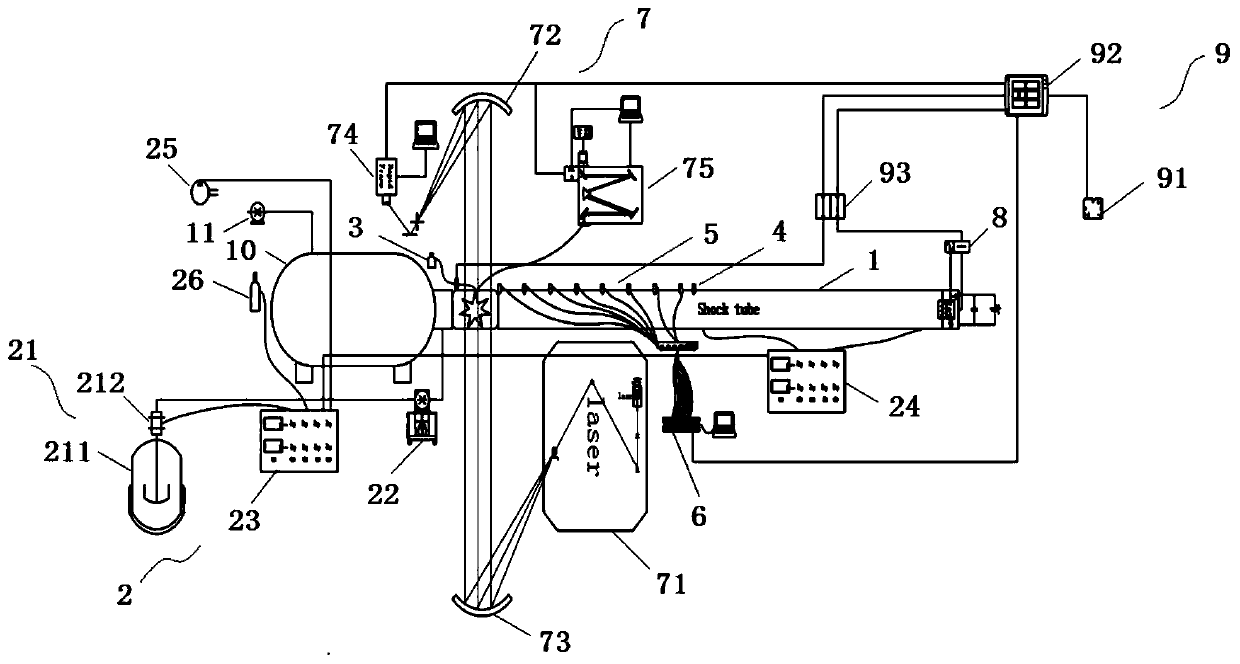
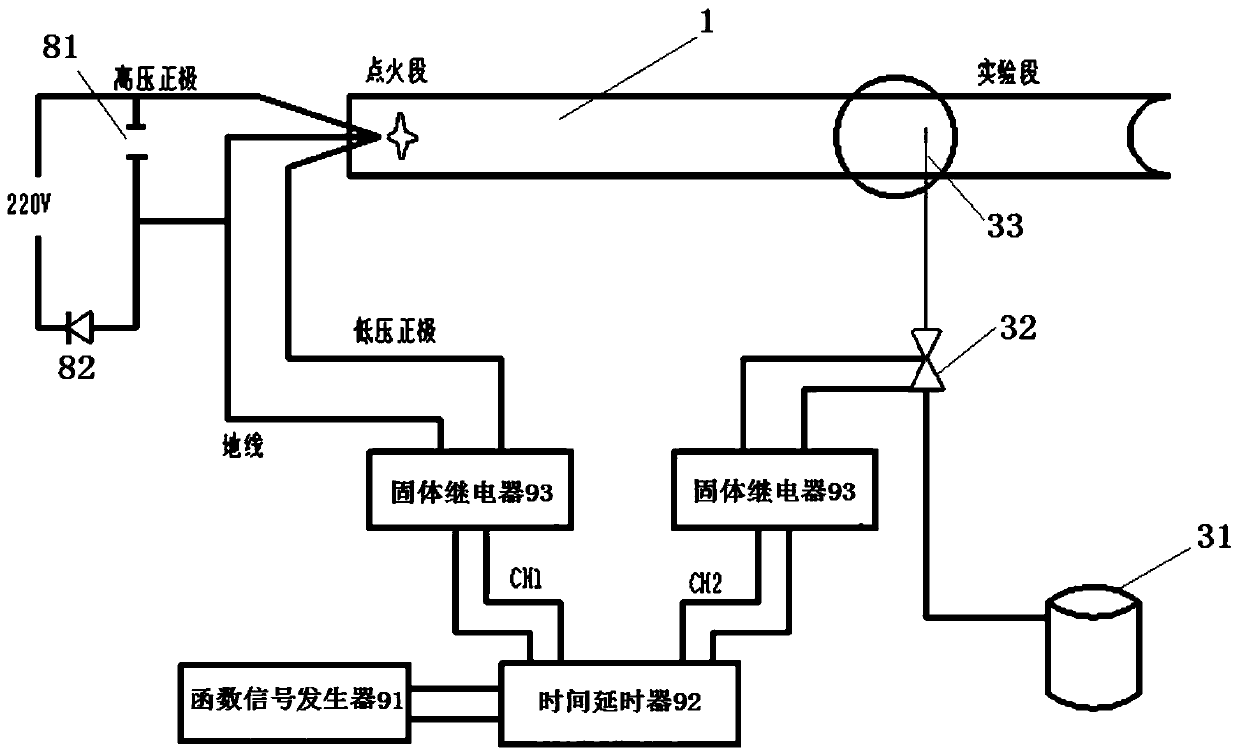
The invention relates to a system and a method for realizing synchronous control of multiple targets in a detonation experiment test system. The system comprises a shock tube, a premixed gas supply system, a flame retardant injection system, a flame signal acquisition system, a pressure signal acquisition system, a data acquisition system, a laser schlieren system, a high-pressure ignition systemand a synchronous control system for controlling the systems, the shock tube comprises a plurality of experiment pipelines and a visual observation window experiment section which are connected in sequence; the premixed gas supply system is communicated with the interior of the shock tube to generate premixed gas with a preset equivalence ratio and input the premixed gas into the shock tube; the flame retardant spraying system is connected with the visual observation window experiment section; the flame signal acquisition system and the pressure signal acquisition system are arranged on the side wall of each section of experiment pipeline; the laser schlieren system is used for measuring distribution images of typical free radical concentration and temperature of the deflagration flow field; the high-pressure ignition system is connected with the end of the shock tube and used for ignition. The system and the method can be widely applied to the field of safety science and technology.

Description

technical field [0001] The invention belongs to the field of safety science and technology, and relates to a system and method for realizing synchronous control of multiple targets in a deflagration experiment test system. Background technique [0002] The deflagration of gas / air premixed gas in coal mines has brought great disasters to mine safety production. At the same time, this kind of problem has always been a classic and frontier problem in the study of mechanics and safety. [0003] In recent years, scholars' research methods can be divided into two categories: numerical simulation research and shock tube experimental research. At present, although the numerical simulation research has been able to reveal the flow phenomenon in the process of flame propagation, it is helpful to understand the transition from laminar flame to turbulent flame, combustion instability and flame shape change, etc., but the calculation results may be affected by the algorithm and mesh The...

Claims


Application Information

Patent Timeline
Patent Type & Authority Applications(China)
IPC IPC(8): G01N25/54
CPCG01N25/54
Inventor 胡洋徐景德何宁张莉聪王晔秦汉圣张延炜
Owner NORTH CHINA INST OF SCI & TECH
Learn More