Pipeline detection method

A detection method and pipeline technology, applied in geophysical measurement, instruments, etc., can solve the problems of lack of tracer lines and electronic tags, and the inability to detect underground pipelines

Active Publication Date: 2020-05-08
核工业二0八大队 +2
View PDF5 Cites 0 Cited by
  • Summary
  • Abstract
  • Description
  • Claims
  • Application Information

AI Technical Summary

Problems solved by technology

[0010] However, most of the PE pipes actually constructed in the early years lacked complete tracer lines and elect

Method used


Image

  • Pipeline detection method
  • Pipeline detection method
  • Pipeline detection method

Examples


Embodiment 1

[0031] Before starting to explore the survey area, pre-set the equipment and conduct a consistency test to ensure that the instruments and equipment used meet the detection accuracy requirements.

[0032] After the on-site calibration is completed, the calibration results should be evaluated. When the calibration results all meet the following conditions, the detector can be put into production.

[0033] Positioning error δts: ≤±0.2h;

[0034] Fixed depth error δth: ≤±0.25

[0035] Note: ①h is the buried depth of the center of the underground pipeline, in centimeters;

[0036] ② When h<100cm, substitute h=100cm into the calculation. (Instrument calibration accuracy and self-inspection accuracy requirements must be higher than acceptance excavation requirements)

[0037] The second part, underground pipeline exploration

[0038] The detection of underground pipelines can be divided into field investigation and instrument detection according to their working methods. Combin...

Embodiment 2

[0067] Applied to the pre-set data obtained in the early stage in embodiment 1, the method in embodiment 2 is the active sound source detection method combined with the brazing method to solve the buried pipe detection, especially suitable for PE pipes.

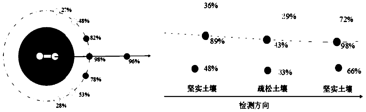
[0068] Step 1. The audio transceiver selects a frequency between 200HZ-1000HZ, sends an audio signal, and the receiver in the audio transceiver receives the signal, searches and records the position of the strongest signal, and uses the position to make a parabolic selection of detection points for detection , when the signal strength connection line of the selected detection point presents a quasi-parabolic shape, and when the point is determined to be the real strongest signal point position, the circular point with the strongest signal position and a radius of 3-5 meters are used to perform circular detection ;

[0069] Specifically: the audio transceiver selects a frequency between 200HZ-1000HZ, sends an audio signal, the...


PUM

PropertyMeasurementUnit
Depthaaaaaaaaaa

Abstract

The invention discloses an active sound source method combined with a drill rod detection method. The method comprises: detecting and verifying a buried gas medium-pressure pipe network and a buried gas low-pressure pipe network; by means of the depth data of the valve well and the drill rod, adjusting the intensity of received signals, meanwhile, obtaining the position information data of the pipeline through circumferential blind measurement, generating GIS data in time. Convenience is brought to pipe network data management of a gas enterprise, and powerful guarantee is provided for datamation and informatization of cities.

Description

technical field [0001] The invention belongs to the detection field of gas pipelines, and aims to solve the data integrity problem of gas pipeline networks. Background technique [0002] The construction of domestic urban gas pipeline network has a history of nearly a hundred years, and most urban gas enterprises were founded in the 1970s. Affected by the construction conditions, technology, and equipment at that time, urban fuel enterprises have the problem of missing completion data to varying degrees. For example, China Resources Gas Group has about 100,000 kilometers of buried pipeline networks, and about one-third of the data is expected to be improved in terms of spatial information and attribute information. [0003] Buried pipe network materials mainly include cast iron pipes, steel pipes, PE pipes, etc. After decades of operation and development, cast iron pipes have basically been modified and withdrawn from application; the detection technology for steel pipes h...

Claims


Application Information

Patent Timeline
IPC IPC(8): G01V11/00
CPCG01V11/00
Inventor 段桂英李喜彬冯来明宋勇张九源薛伟戴明建李华明齐彥宏孙长亮覃宗耀
Owner 核工业二0八大队
Why Eureka
Try Eureka