Damping component of large self-unfolding satellite antenna
A satellite antenna and self-deploying technology, which is applied to antenna components, antennas, folding antennas, etc., can solve the problems of large energy consumption due to nonlinear frictional vibration, control frequency bandwidth, etc., and meet the requirements of ensuring lightweight, control frequency bandwidth, and power consumption can have a big effect
- Summary
- Abstract
- Description
- Claims
- Application Information
AI Technical Summary
Problems solved by technology
Method used
Image
Examples
specific Embodiment approach 1
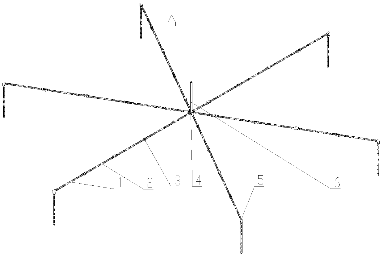
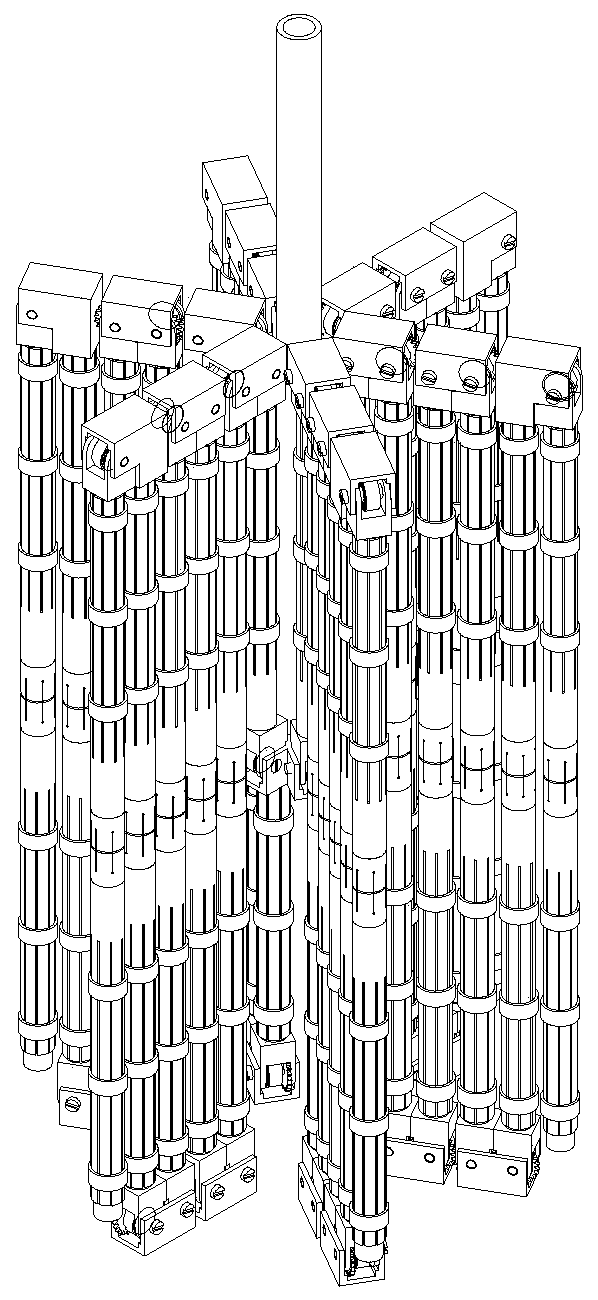
[0032] Specific implementation mode one: combine Figure 1-Figure 9To illustrate, take the radial rib satellite antenna as an example to introduce the vibration damping member of the large self-deploying satellite antenna of the present invention. The damping member of the large-scale self-deploying satellite antenna of the present invention comprises four parts: a self-resetting axial damper 1, a multi-finger flap friction damper 2, a folding hinge assembly 3, and a support rod 12; the support rod 12 serves as The basic structural parts are respectively connected to the self-resetting axial damper 1 and the folding hinge assembly 3, and serve as the base body of the multi-finger valve pressure plate 11, and are connected to the multi-finger valve pressure plate 11 through the outer ring locking ring 10 to jointly form a multi-finger valve Damper assembly 2. The radial rib assembly A is formed by sequentially connecting the shock-absorbing components of six large self-deployi...
specific Embodiment approach 2
[0033] Specific implementation mode two: combination Figure 4 , Figure 5 Explain that the self-resetting axial damper 1 of the present embodiment is composed of an outer sleeve 8, a damping energy dissipation element 9, a shape memory alloy wire 7 and a guide shaft 19. The two outer sleeves 8 are butted, and the annular metal rubber 9 is passed and fixed between the two outer sleeves as a damping energy dissipation element by a guide shaft 19. The guide shaft 19 can ensure the radial stiffness and vibration direction of the damper. The shape memory alloy wire 7 has superelastic mechanical properties, and provides axial preload for the metal rubber 9 of the axial damper 1 by being wound on the two outer sleeves 8. When vibration occurs, the vibration will cause the two outer sleeves to The relative position between the sleeves 8 changes, thereby causing the stretching or compression of the metal rubber 9, and the thin metal wires in the metal rubber 9 rub against each other ...
specific Embodiment approach 3
[0034] Specific implementation mode three: combination image 3 , Figure 6 Explain that the multi-finger flap damper 2 of the present embodiment adopts the carbon fiber multi-finger flap thin-walled ring cross-section structure of the same material as the support rod 12 as the multi-finger flap pressure plate 11, and the root of one end of the damping structure is not divided into flaps, and is fixed to the hinged end of the expansion member. Together, the remaining parts are multi-finger valve structures, and are pre-pressed on the outer wall of the expansion member through the outer ring locking ring 10 . When the support bar 12 vibrates laterally, because the vibration and deformation of the multi-finger platen 11 and the structural bar 6 are different in size, relative displacement will occur between the two, and the outer locking ring 11 will be multi-finger through the pre-tightening force. The damper 2 exerts a frictional force, so frictional energy will be generated ...
PUM
 Abstract
Description
Claims
Application Information
 - R&D
- Intellectual Property
- Life Sciences
- Materials
- Tech Scout
- Unparalleled Data Quality
- Higher Quality Content
- 60% Fewer Hallucinations
Browse by: Latest US Patents, China's latest patents, Technical Efficacy Thesaurus, Application Domain, Technology Topic, Popular Technical Reports.
© 2025 PatSnap. All rights reserved.Legal|Privacy policy|Modern Slavery Act Transparency Statement|Sitemap|About US| Contact US: help@patsnap.com


