Supercharge Your Innovation With Domain-Expert AI Agents!

Motor control method based on single Hall sensor

A hall sensor, motor control technology, applied in the direction of electronic commutator, etc., can solve the problems of unreliable, motor control failure, no brushless motor, etc., to ensure reliable operation, ensure reliable operation, and occupy a small space Effect

Inactive Publication Date: 2020-05-08
KEBODA TECH CO LTD
View PDF0 Cites 0 Cited by
  • Summary
  • Abstract
  • Description
  • Claims
  • Application Information

AI Technical Summary

Problems solved by technology

[0005] 1. The three Hall sensors themselves need to occupy a large space, which will lead to difficulties in hardware design for applications with extremely high space requirements;
[0006] 2. The three Hall sensors have strict requirements on the position (the phase difference requires 120°), which increases the requirements on the accuracy of the production process;
[0007] 3. The price of the three Hall sensors is relatively high, which increases the cost
These methods are simple in structure and low in cost, but their reliability deteriorates, which affects the safe use of the system. The reasons are as follows:
[0009] 1. During the start-up process, there is no real rotor position information of the brushless motor, the start-up reliability is low, and start-up failure is a high-probability event;
[0010] 2. After the failure to start, since the information does not have the real rotor position for reference (especially the first method), the single-chip microcomputer cannot accurately judge the failure of the motor to start, resulting in the failure of the motor control;
[0011] 3. In the process of starting, since the rotor position is given artificially, it cannot truly reflect the actual angle of the motor.
For some driving structures, this error will accumulate more and more, thus affecting the performance of the entire system;
[0012] 4. When the load of the motor suddenly increases, the actual speed of the motor will drop rapidly or even stop due to the low accuracy of position information judgment;
[0013] 5. When the moving part driven by the motor encounters an obstacle, the first method can only be judged indirectly through the AD current collection method, which is time-consuming and not necessarily reliable; the second and third methods can make judgments by estimating position information, but Since the counter electromotive force is very small at low speeds, it is basically not usable, which leads to the possibility of misjudgment.

Method used


Image

  • Motor control method based on single Hall sensor
  • Motor control method based on single Hall sensor
  • Motor control method based on single Hall sensor

Examples


Embodiment Construction

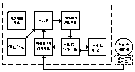
[0029] According to a motor control method based on a single Hall sensor according to an embodiment of the present invention, the single Hall sensor is used to detect the position of the motor rotor, and the motor control method based on a single Hall sensor includes the following steps:

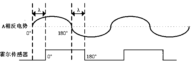
[0030] a. Measure the phase difference λ between any opposite potential of the motor and the output signal of a single Hall sensor;

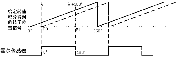
[0031] b. Given the speed Vn of the motor, output a voltage or current signal to the motor to start the motor, and obtain the theoretical position Pn of the rotor by integrating the given speed Vn;

[0032] c. When the rising edge of the output signal of a single Hall sensor is detected, use λ to correct the theoretical rotor position obtained by integration, so that the theoretical value P0 of the rotor position at the moment when the rising edge is detected is equal to λ, and P0 is used as Based on the subsequent rotor position integral calculation;

[0033...


PUM


Abstract

The invention discloses a motor control method based on a single Hall sensor. The motor control method comprises the following steps: a, measuring a phase difference [lambda] between any phase counterpotential of a motor and the output signal of the single Hall sensor; b, giving the rotating speed Vn of the motor, starting the motor, and obtaining the theoretical rotor position Pn by integratingthe given rotating speed Vn; c, when the rising edge of the output signal of the single Hall sensor is detected, correcting the theoretical rotor position obtained through integration by using [lambda], so that the theoretical value P0 of the rotor position at the moment when the rising edge is detected is equal to [lambda]; and d, when the falling edge of the output signal of the single Hall sensor is detected, correcting the theoretical rotor position obtained through integration by [lambda]+180 degrees, so that the theoretical value P1 of the rotor position at the moment when the falling edge is detected is equal to [lambda]+180 degrees. According to the invention, the rotor position precision estimated based on a motor control mode without a position sensor is improved, and the reliability of position-free control is improved.

Description

technical field [0001] The invention relates to motor control technology. Background technique [0002] figure 1 A functional block diagram of an existing motor controller for driving a permanent magnet brushless motor is shown. As shown in the figure, the motor controller includes a power management unit, a communication unit, a single chip microcomputer, a PWM signal generating unit, a three-phase bridge pre-driver circuit, a three-phase bridge circuit and a sensor signal processing unit. [0003] Among them, the power management unit is used to provide power for the entire motor controller. The communication unit is mainly responsible for the communication between the motor controller and the upper controller. The single-chip microcomputer receives the instructions of the upper controller, and feeds back the corresponding state to the upper controller, and controls the permanent magnet brushless motor to perform corresponding actions according to the received instructi...

Claims


Application Information

Patent Timeline
Patent Type & Authority Applications(China)
IPC IPC(8): H02P6/16
CPCH02P6/16
Inventor 李诗念黄左韵阳彩
Owner KEBODA TECH CO LTD
Features
  • R&D
  • Intellectual Property
  • Life Sciences
  • Materials
  • Tech Scout
  • Unparalleled Data Quality
  • Higher Quality Content
  • 60% Fewer Hallucinations
Learn More