MEMS diaphragm and MEMS sensor chip

A diaphragm and sensing part technology, applied in piezoelectric devices/electrostrictive devices, semiconductor/solid-state device components, piezoelectric/electrostrictive/magnetostrictive devices, etc. control of film stress, low sensitivity of MEMS devices, etc.

Active Publication Date: 2020-05-12
SHANDONG GETTOP ACOUSTIC
View PDF3 Cites 2 Cited by
  • Summary
  • Abstract
  • Description
  • Claims
  • Application Information

AI Technical Summary

Problems solved by technology

Among them, the material properties of the sensing film determine the sensitivity performance of the component, but the thermal residual stress generated in the semiconductor processing pro

Method used


Image

  • MEMS diaphragm and MEMS sensor chip
  • MEMS diaphragm and MEMS sensor chip
  • MEMS diaphragm and MEMS sensor chip

Examples


Embodiment Construction

[0033] Before describing the embodiments in detail, it should be understood that the present invention is not limited to the detailed structures or arrangements of components described herein below or in the accompanying drawings. The present invention can be implemented in other ways. Also, it should be understood that the phraseology and terminology used herein are for descriptive purposes only and should not be interpreted as limiting. The terms "including", "comprising", "having" and similar expressions used herein are meant to include the items listed thereafter, their equivalents and other additional items. In particular, when "a certain component" is described, the present invention does not limit the number of the component to one, and may also include multiples.

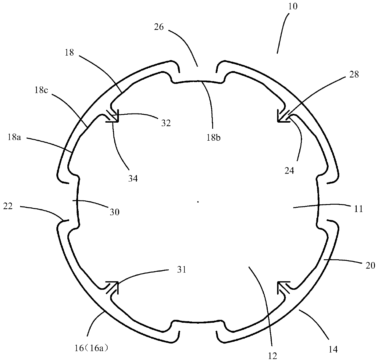
[0034] Such as figure 1 Shown is a schematic structural diagram of the MEMS diaphragm in an embodiment of the present invention. The MEMS diaphragm 10 is applied in microelectromechanical devices, for exa...


PUM


Abstract

The invention provides an MEMS diaphragm and an MEMS sensor chip. The MEMS diaphragm comprises a sensing part and a peripheral part surrounding the periphery of the sensing part. A plurality of outergrooves and a plurality of inner grooves are formed between the peripheral part and the sensing part; the plurality of outer grooves are annularly distributed at the inner edge of the peripheral part;a first connecting arm is formed between every two adjacent outer grooves, the multiple inner grooves are annularly distributed in the outer edge of the sensing part, a second connecting arm is formed between every two adjacent inner grooves, and at least one of the first connecting arms and the second connecting arms is provided with a reinforcing rib structure.

Description

technical field [0001] The invention relates to the technical field of micro-electromechanical systems (MEMS, Micro-Electro-Mechanical System), in particular to a MEMS diaphragm and a MEMS sensor chip including the MEMS diaphragm. Background technique [0002] Micro-electromechanical sensors are widely used in various acoustic receivers or force sensors. Their small size, low power consumption, and high sensitivity have become design goals. According to the results of theoretical simulations, the influence of residual stress on sensors The mechanical sensitivity of the diaphragm in the vibrating film has a great influence. [0003] The capacitive sensor structure included in the MEMS device is generally a sensing film and a back electrode, forming a two-parallel capacitive plate structure to sense vibration or pressure change. Among them, the material properties of the sensing film determine the sensitivity performance of the component, but the thermal residual stress gener...

Claims


Application Information

Patent Timeline
IPC IPC(8): B81B7/02B81B3/00
CPCB81B7/02B81B3/0021B81B3/0072B81B2201/0221
Inventor 何宪龙
Owner SHANDONG GETTOP ACOUSTIC
Why Eureka
Try Eureka